
Xiuhua Fu, Cheng Chen, Zhanggui Hu, Shifu Xiong, Jing Zhang, Fei Wang, Chenxin Wang. Development of Separation Film for Frequency Doubling in 278 nm All-Solid-State Laser System[J]. Chinese Journal of Lasers, 2019, 46(12): 1203002
- Chinese Journal of Lasers
- Vol. 46, Issue 12, 1203002 (2019)
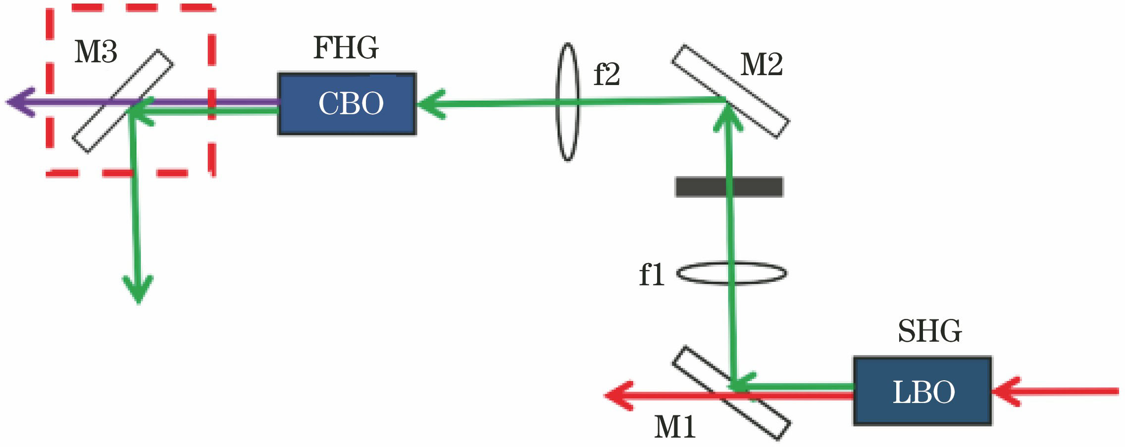
Fig. 1. Optical path diagram of frequency doubling modulation of 278 nm all-solid-state laser system
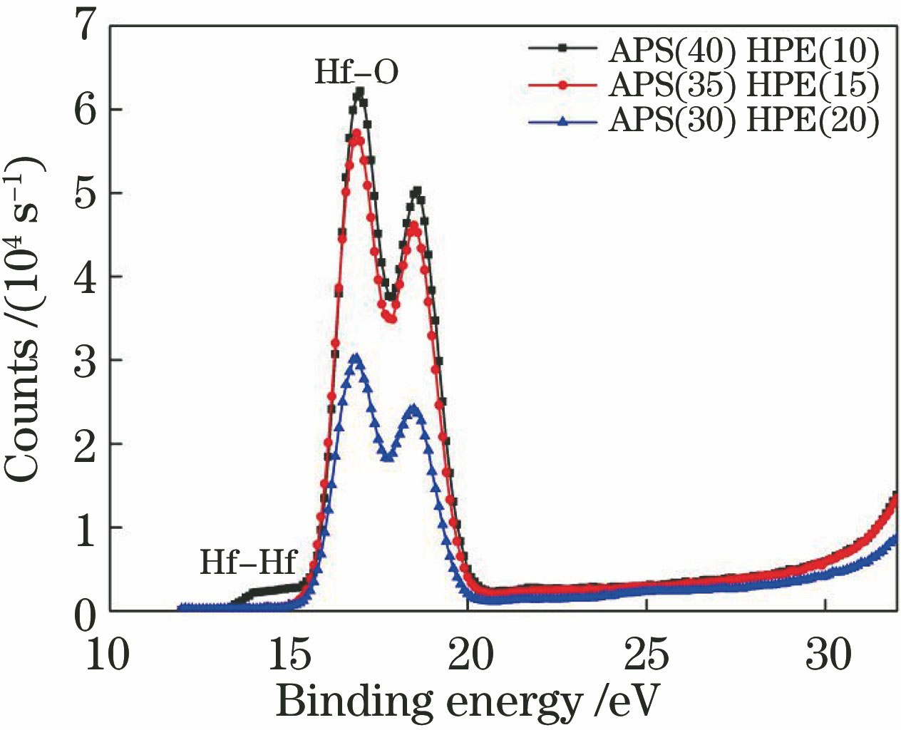
Fig. 2. X-ray photoelectron spectroscopy of hafnium
Fig. 3. Optical constants of HfO2 film. (a) Refractive index; (b) extinction coefficient
Fig. 4. Three-dimensional morphologies of UV-SiO2 films at different deposition rates. (a) 0.5 nm/s; (b) 0.7 nm/s; (c) 0.9 nm/s
Fig. 5. Optical constants of thin film materials. (a) HfO2 film; (b) UV-SiO2 film
Fig. 6. Relationship between electric field intensity and film period at film/air interface
Fig. 7. Theoretically spectral curve of front surface
Fig. 8. Theoretically spectral curve of back surface
Fig. 9. Theoretically transmittance spectral curve of double-side design
Fig. 10. Three-dimensional curves of theoretical design of separation film for frequency doubling at different wavelengths. (a) At 278 nm; (b) at 556 nm
Fig. 11. Transmission test curves of single-side coating. (a) Front surface; (b) back surface
Fig. 12. Spectral test curves of double-side coating. (a) Transmittance; (b) reflectivity
Fig. 13. Measured spectrum as a function of incident angle
Fig. 14. Laser induced damage threshold
| |||||||||||||||
Table 1. Technical parameters of beam splitter
|
Table 2. Scheme for oxygen distribution
|
Table 3. Surface roughness of UV-SiO2 film at different deposition rates
| ||||||||||||||||||||
Table 4. Process parameters of deposition of Hf and UV-SiO2 films
|
Table 5. Ion source process parameters of Hf and UV-SiO2
|
Table 6. Damage probability corresponding to laser with different energy densities

Set citation alerts for the article
Please enter your email address
© Copyright 2018-2021 | Chinese Laser Press. All Rights Reserved 沪ICP备15018463号-20