
Clement Deleau, Han Cheng Seat, Olivier Bernal, Frederic Surre, "High-sensitivity integrated SiN rib-waveguide long period grating refractometer," Photonics Res. 10, 564 (2022)
- Photonics Research
- Vol. 10, Issue 2, 564 (2022)
Abstract
1. INTRODUCTION
Since their invention, refractometers have emerged as critical metrological tools extensively employed in industry for a broad range of applications, from chemical analysis [1] to temperature and strain sensing [2]. Refractometry-based sensors allow the estimation of the targeted physical or chemical parameter of interest via the optical measurement of its corresponding refractive index (RI). The inherent high versatility achievable among the wide variety of optical transducers contributes to driving research on refractometers toward increasingly higher sensitivities, resolution, and linearity. As the fundamental basis of many optical sensing solutions, refractometry has also been recently investigated for device implementation on the integrated photonic platform as a pathway to potentially achieve even higher performances while reducing the system’s footprint [3]. Integrated silicon-based photonic sensors intrinsically benefit from major features such as electromagnetic immunity, compactness, and miniaturization, as well as their high flexibility of design [4]. These characteristics thus render the CMOS-compatible platform very attractive for high performance sensing schemes that require high resolution and precision while being cost effective. Integrated refractometers could be typically classified into five different categories: waveguide interferometers [5], resonators [6], photonic crystals [7], plasmonic devices [8], and diffraction gratings [9].
Long period gratings (LPGs) form a sub-family of the grating-based group. They consist of structures that operate on the exchange of energy between two or more co-propagative optical modes. This coupling is allowed by a periodic exchange of energy when the grating period and propagated wavelength satisfy a resonance condition. LPGs have been mainly investigated as fiber-based sensors because they allow optical energy to interact with the external environment by coupling a buried core mode to a leaking cladding mode [10] exposed to the external medium [11]. Any modification of the RI in the external environment results in a shift of a resonance wavelength. Their simplicity of fabrication using fiber tapering, irradiation, corrugation, inscription, or arc discharge has also rendered them attractive for mass fabrication. Moreover, LPGs have recently been subject to increasing interest for implementation in integrated photonics [12–16] due to their very high sensitivity potential, small footprints, and specific features that can be exploited on a design-flexible platform. In fact, when compared to typical interferometers or resonators, which exhibit periodic spectral patterns [17], LPGs offer the particular ability to create a localized spectral response while having similar performance potential. Obtaining such localized patterns is particularly advantageous, as it greatly facilitates the tracking of the LPG’s spectral signature in highly sensitive refractometers.
In this work, we propose an integrated refractometric sensor operating on a long period waveguide grating (LPWG) implemented on a planar rib waveguide whose core width is sinusoidally modulated. Contrary to other optimization methods that generally improve the local sensitivity performance only around a narrow range of a few nanometers [14,18], we aim to show here that sensitivity can be uniformly enhanced over a broader spectrum by following certain design guidelines. This is performed on our structure by tailoring the effective indices of the coupled modes while simultaneously tuning the mode coupling strength. In Section 2, the LPWG sensing scheme is theoretically discussed and explained, and the design optimization method exploiting effective index (EI) tailoring is next described for sensitivity performance enhancement. In Section 3, the proposed architecture is detailed and modeled using modal analysis and eigenmode expansion (EME). The fabrication and characterization processes are then described in Section 4. Experimental results from optical refractometric measurements are subsequently presented and discussed in Section 5.
Sign up for Photonics Research TOC. Get the latest issue of Photonics Research delivered right to you!Sign up now
2. OPERATING PRINCIPLES
A. Long Period Grating Theory
LPGs are waveguide-based structures that employ periodic modulation to enable energy exchange between co-propagative optical modes. As each mode possesses a specific propagation constant and behavior, LPGs are designed to selectively couple modes at resonance wavelengths, as described by the phase-matching condition [19]
B. Long Period Grating as Refractometer
Perturbation of the optical system typically occurs through the interaction of the evanescent field of a mode with the target analyte, which results in modification of the propagation constants of the mode as a function of RI variation. As defined by Eq. (1), the central wavelength of the resonance
Generally, LPG sensing systems rely on a wavelength interrogation technique. The sensitivity
Two sensitivity improvement techniques have been previously employed in the design of integrated LPGs, namely, modal interaction optimization [12,15] and phase-matching turning-point (PMTP) optimization [14]. Modal interaction optimization relies on maximizing the sensing region’s influence on the difference
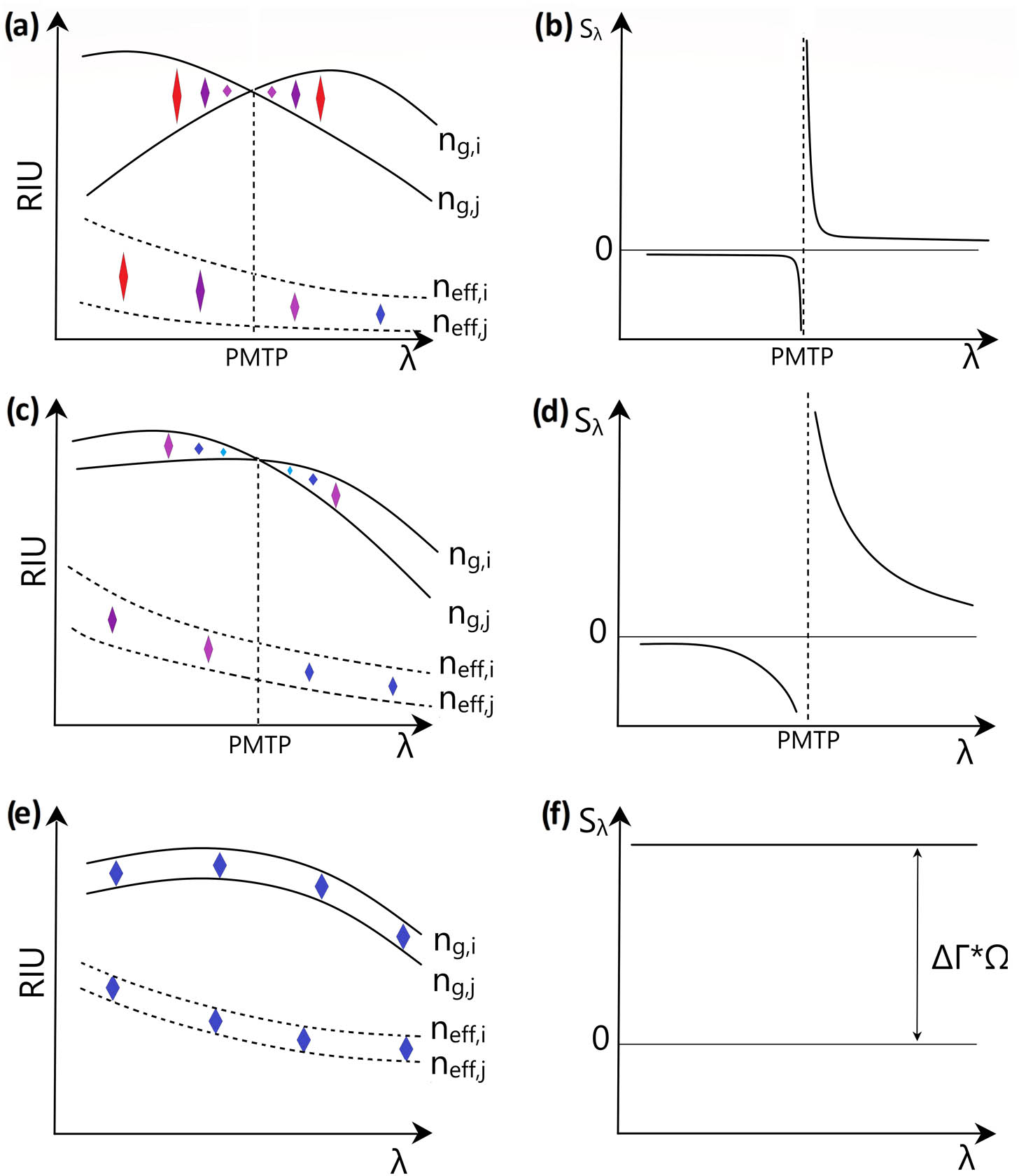
Figure 1.Illustration of spectral sensitivity optimization behavior. (a), (c), (e) Different propagation constant spectral profiles and (b), (d), (f) subsequent expected sensitivity behavior versus wavelength.
Optimization is typically performed by displacing the PMTP near the wavelength of interest using GI tuning to increase the
To circumvent this issue, we propose in this research another method based on the tailoring of the coupling modes so that the coupled modes’ chromatic dispersion behaviors and EIs could be brought as close as possible. This should result in a sensitivity improvement similar to the PMTP method, with the additional characteristic of the resulting sensitivity response remaining almost constant over a much wider wavelength measurement range, as illustrated in Figs. 1(e) and 1(f). In this case,
In addition to the sensitivity, the full-width at half-maximum (FWHM) can be utilized for comparing refractometric schemes, as it can provide insight on the resolution achievable in tracking both the induced resonance location and shift, thus accounting for the sensor performance. FWHM can be estimated as follows [25]:
C. Proposed Structure
The proposed structure consists of a partially covered silicon nitride (SiN) hybrid rib–strip waveguide of RI
![]()
Figure 2.Illustration of the implemented rib waveguide LPG structure with sinusoidally modulated width.
![]()
Figure 3.Simulated mode profiles for a rib LPWG: HE1 (top) and HE7 (bottom).
3. DESIGN OPTIMIZATION AND LPWG ARCHITECTURE
A standard 400 nm SiN core thickness,
The following subsections describe the LPWG structural parameters that are chosen. In this research, we employ Lumerical’s mode solver to simulate the rib LPWG [27] for which the mesh resolution has been set at 1 nm in the core region and surrounding interfaces. Note that both metal and perfectly matched layer boundary conditions lead to identical results, as they are positioned sufficiently far from the waveguide.
![]()
Figure 4.LPG cross-sectional profile.
A.
As previously described,
B. Slab Thickness
We observe that the etch depth,
![]()
Figure 5.Coupling modes’ EI difference and waveguide sensitivity
C. Slab Width
Mode calculations suggest that the EIs of slab modes tend to increase and approach the EI of the fundamental mode with increasing slab width (
![]()
Figure 6.Simulated effective and group indices of modes HE1 and HE7 showing similar dispersion with
D. Core Width
The core width is found to have little effect on the EIs of both core and slab modes when tuned between 1 and 3 μm. Nevertheless, two criteria have to be taken into account for the proper design of the LPWG. First, single mode propagation within the core region has to be ensured to minimize
![]()
Figure 7.Coupling parameter and estimated full coupling length versus core width with
E. LPWG Period and Length
As described by Eq. (1), when the EIs of the coupling modes are closer, the LPWG period greatly increases. To couple the HE1 and HE7 modes around 1550 nm, whose EIs are found to be, respectively, 1.693 and 1.673, the period has to be set to
![]()
Figure 8.Resonance spectra simulated with EME for different LPWG lengths with a period of 77.5 μm,
4. FABRICATION
A. Layout
To facilitate optical injection into the photonic chip, standard grating couplers are used, as they enable easy characterization of the optical structures [4]. Fundamental mode coupling in the rib waveguide is then performed using 50 μm long strip–rib tapers at both ends of the LPWG [29]. Since fabrication defaults due to both variations of material RIs and geometrical dimensions of the patterned waveguides, and also high sensitivity (
![]()
Figure 9.Layout of the designed photonic chip showing (a) strip–rib converter, (b) LPWG, and (c) grating coupler.
B. Process
As illustrated in Fig. 10, a
![]()
Figure 10.Illustration of LPWG fabrication process.
C. Structure Characterization
The rib LPWGs are first physically characterized using a scanning electron microscope (SEM) as seen in Fig. 11(d). A transverse shift of 600 nm is observed on the second patterned layer. This 600 nm off-alignment is reintroduced into the simulation model and found to cause a minor resonance shift of
![]()
Figure 11.SEM pictures of photonic circuit components: (a) strip–rib converter; (b) grating coupler, (c) LPWG section, and (d) minor misalignment between strip and rib waveguides shown here at the beginning of the tapering region for the sake of clarity.
5. EXPERIMENTAL RESULTS
A. Experimental Setup
The experimental setup for optical characterization consists of a Santec TSL550 tunable laser source, a fiber array mounted on a motorized linear stage driven by a dedicated LabVIEW program, and an optical powermeter, as illustrated in Fig. 12. The injection and recovery of the interrogating light into the photonic circuit is obtained by positioning the fiber array on top of a chip-integrated grating coupler pair. The injected laser wavelength is next scanned over the spectral region of interrogation from which the transmission spectrum is then measured. The transmission spectra of the LPWGs are obtained after de-embedding the transmitted signal to isolate both the LPWG’s and tapers’ spectral contributions from those of the grating couplers, tunable laser output, and lead-in/lead-out waveguides. It is first observed during optical characterization of the LPWGs that the background loss of
![]()
Figure 12.Illustration of the experimental photonic characterization setup.
B. Sensitivity
Commercially available liquids of calibrated RIs from Cargill are employed and mixed into different proportions to simulate indices varying between 1.33 and 1.35 RIUs. These RIs are first measured using a commercial Hanna HI 96801 refractometer with a resolution of 0.2 mRIU. The optical liquids are then deposited on top of the chip to induce RI variations in the LPWG resonance, which is subsequently tracked over a spectral window of 100 nm. Resonance features observed during the optical characterization of an LPWG with a 77.5 μm period, as shown in Fig. 13, exhibit a 3 dB bandwith of 25 nm and an extinction ratio of 10–12 dB, which are very similar to the simulated values. Figure 14 plots the simulated and experimental resonance wavelength of the LPWG against the analyte’s RI, from which the sensitivity calculated as the slope can be extracted. Here, the experimentally measured sensitivity is estimated to be
![]()
Figure 13.(a) Simulated and (b) experimentally measured normalized resonance spectra at surface RIs of 1.3388 and 1.34.
![]()
Figure 14.Simulated and measured resonance wavelength of LPWGs obtained for different surface RIs.
Table 1 summarizes the sensitivities and specific properties of our proposed structure in comparison with previously reported fabricated LPWGs. Other LPWG designs based on waveguide sensitivity enhancement [12,16] or the PMTP optimization technique [14] exhibit either limited sensitivity enhancement or measurement range, respectively. On the other hand, our proposed sensor demonstrates ultrahigh sensitivity that, more significantly, is found to remain constant over a broad measurement range.
Comparison with Other Fabricated LPWGs
| References | Material | Structure Type | LPG Length | Measured Sensitivity | FWHM | Period |
|---|---|---|---|---|---|---|
| [ | Silicon nitride | Polymer waveguide coupling | 1000 | 240–900 | 5 | 10 |
| [ | BK-7 glass | Rib waveguide | 1915 | 240 | 3 | 180 |
| [ | Silicon nitride | Strip–slot waveguide coupling | 2000 | 1970 | 7 | 15.1 |
| [ | Silicon | Asymmetric strip waveguide | 1500 | 5078 | 20–30 | 7.8 |
C. Temperature Dependence
To study the influence of temperature on our structure, the thermo-optic coefficients of SiN and
![]()
Figure 15.Experimental wavelength resonance pattern shifts with temperature of the LPWG.
![]()
Figure 16.Simulated and measured resonance wavelength variations versus temperature of the LPWG.
6. CONCLUSION
Integrated refractometers are under intense investigation as the current state of the art in nano-fabrication lends unprecedented flexibility in the design of wavelength-scale complex photonic structures. In this paper, we proposed a novelty integration of a structure typically implemented on fiber platforms, i.e., the LPG. Indeed, alongside interferometers, LPWGs are photonic structures that benefit most from current advances in waveguide manufacturing technology [32], as their performance ultimately scales to the propagation length. However, unlike high-sensitivity interferometers for which the analysis of their spectral shift is complicated by the output spectral periodicity, LPWGs, on the other hand, which present localized spectral patterns, are promising candidates for constructing ultrahigh performance refractometers. The proposed structure, consisting of a rib-waveguide LPG, has been designed, fabricated, and characterized. A very high sensitivity of
Acknowledgment
Acknowledgment. All fabrication and characterization of the integrated photonic long period waveguide gratings were supported by both TTIL 2019 (Toulouse Tech Interlabs) and RENATECH (French Network of Technology Platforms) within LAAS-CNRS cleanroom infrastructure. The authors thank A. Lecestre, F. Carcenac, J.-B. Doucet, and L. Mazenq for their technical assistance with the fabrication and characterization process of the photonic integrated circuits.
References
[1] A. Urrutia, I. Del Villar, P. Zubiate, C. Zamarreño. A comprehensive review of optical fiber refractometers: toward a standard comparative criterion. Laser Photon. Rev., 13, 1900094(2019).
[2] M. Ramakrishnan, G. Rajan, Y. Semenova, G. Farrell. Overview of fiber optic sensor technologies for strain/temperature sensing applications in composite materials. Sensors, 16, 99(2016).
[3] E. Luan, H. Shoman, D. M. Ratner, K. C. Cheung, L. Chrostowski. Silicon photonic biosensors using label-free detection. Sensors, 18, 3519(2018).
[4] L. Chrostowski, M. Hochberg. Silicon Photonics Design: From Devices to Systems(2015).
[5] X. Guan, L. H. Frandsen. All-silicon interferometer with multimode waveguides for temperature-insensitive filters and compact biosensors. Opt. Express, 27, 753-760(2019).
[6] S. Chandran, R. K. Gupta, B. K. Das. Dispersion enhanced critically coupled ring resonator for wide range refractive index sensing. IEEE J. Sel. Top. Quantum Electron., 23, 424-432(2017).
[7] P. Xu, J. Zheng, J. Zhou, Y. Chen, C. Zou, A. Majumdar. Multi-slot photonic crystal cavities for high-sensitivity refractive index sensing. Opt. Express, 27, 3609-3616(2019).
[8] E. Chatzianagnostou, A. Manolis, G. Dabos, D. Ketzaki, A. Miliou, N. Pleros, L. Markey, J.-C. Weeber, A. Dereux, B. Chmielak, A.-L. Giesecke, C. Porschatis, P. J. Cegielski, D. Tsiokos. Scaling the sensitivity of integrated plasmo-photonic interferometric sensors. ACS Photon., 6, 1664-1673(2019).
[9] X. Wang, J. Flueckiger, S. Schmidt, S. Grist, S. T. Fard, J. Kirk, M. Doerfler, K. C. Cheung, D. M. Ratner, L. Chrostowski. A silicon photonic biosensor using phase-shifted Bragg gratings in slot waveguide. J. Biophoton., 6, 305-828(2013).
[10] E. Simões, I. Abe, J. Oliveira, O. Frazão, P. Caldas, J. Pinto. Characterization of optical fiber long period grating refractometer with nanocoating. Sens. Actuators B, 153, 335-339(2011).
[11] H. Hu, C. Du, Q. Wang, X. Wang, Y. Zhao. High sensitivity internal refractive index sensor based on a photonic crystal fiber long period grating. Instrum. Sci. Technol., 45, 181-189(2016).
[12] Q. Liu, Z. Gu, M. K. Park, J. Chung. Experimental demonstration of highly sensitive optical sensor based on grating-assisted light coupling between strip and slot waveguides. Opt. Express, 24, 12549-12556(2016).
[13] U. Tripathi, V. Rastogi. Temperature insensitive long period waveguide gratings in rib waveguide. Optik, 186, 15-21(2019).
[14] J. Høvik, M. Yadav, J. W. Noh, A. Aksnes. Waveguide asymmetric long-period grating couplers as refractive index sensors. Opt. Express, 28, 23936-23949(2020).
[15] C. Deleau, H. Seat, H. Tap, F. Surre, O. Bernal. Integrated silicon nitride horizontal long period grating for refractometric gas sensing applications. IEEE International Instrumentation and Measurement Technology Conference (I2MTC), 1-6(2020).
[16] C. Deleau, H. C. Seat, H. Tap, F. Surre, O. D. Bernal. Integrated width-modulated sin long period grating designed for refractometric applications. J. Lightwave Technol., 39, 4820-4827(2021).
[17] M. Kitsara, K. Misiakos, I. Raptis, E. Makarona. Integrated optical frequency-resolved Mach-Zehnder interferometers for label-free affinity sensing. Opt. Express, 18, 8193-8206(2010).
[19] H. Taylor, A. Yariv. Guided wave optics. Proc. IEEE, 62, 1044-1060(1974).
[20] A. W. Snyder, J. Love. Optical Waveguide Theory(2012).
[21] G. Veldhuis, O. Parriaux, H. Hoekstra, P. Lambeck. Sensitivity enhancement in evanescent optical waveguide sensors. J. Lightwave Technol., 18, 677-682(2000).
[22] T. MacDougall, S. Pilevar, C. Haggans, M. Jackson. Generalized expression for the growth of long period gratings. IEEE Photon. Technol. Lett., 10, 1449-1451(1998).
[23] E. A. J. Marcatili. Modal dispersion in optical fibers with arbitrary numerical aperture and profile dispersion. Bell Syst. Tech. J., 56, 49-63(1977).
[24] X. Shu, L. Zhang, I. Bennion. Sensitivity characteristics of long-period fiber gratings. J. Lightwave Technol., 20, 255-266(2002).
[25] L. Rindorf, O. Bang. Sensitivity of photonic crystal fiber grating sensors: biosensing, refractive index, strain, and temperature sensing. J. Opt. Soc. Am. B, 25, 310-324(2007).
[26] Q. Liu, K. S. Chiang, K. P. Lor. Condition for the realization of a temperature-insensitive long-period waveguide grating. Opt. Lett., 31, 2716-2718(2006).
[27] http://www.lumerical.com. http://www.lumerical.com
[28] D. Gallagher, T. Felici. Eigenmode expansion methods for simulation of optical propagation in photonics - pros and cons. Proc. SPIE, 4987, 69-82(2003).
[29] T. Aalto, K. Solehmainen, M. Harjanne, M. Kapulainen, P. Heimala. Low-loss converters between optical silicon waveguides of different sizes and types. IEEE Photon. Technol. Lett., 18, 709-711(2006).
[30] C. W. Holzwarth, T. Barwicz, H. I. Smith. Optimization of hydrogen silsesquioxane for photonic applications. J. Vac. Sci. Technol. B, 25, 2658-2661(2007).
[31] A. Arbabi, L. Goddard. Measurements of the refractive indices and thermo-optic coefficients of Si3N4 and SiO
[32] M. H. P. Pfeiffer, J. Liu, A. S. Raja, T. Morais, B. Ghadiani, T. J. Kippenberg. Ultra-smooth silicon nitride waveguides based on the damascene reflow process: fabrication and loss origins. Optica, 5, 884-892(2018).


Set citation alerts for the article
Please enter your email address

© Copyright 2018-2021 | Chinese Laser Press. All Rights Reserved 沪ICP备15018463号-20