• Photonics Research
  • Vol. 11, Issue 6, 978 (2023)
Sen Mou1、*, Luca Tomarchio2, Annalisa D’Arco1、3, Marta Di Fabrizio2, Salvatore Macis2, Alessandro Curcio4, Luigi Palumbo1、3, Stefano Lupi2、5, and Massimo Petrarca1、3
Author Affiliations
  • 1INFN-Roma1 and Physics Department, University of Rome “La Sapienza”, 00185 Rome, Italy
  • 2Physics Department, University of Rome “La Sapienza”, 00185 Rome, Italy
  • 3SBAI, Department of Basic and Applied Sciences for Engineering, University of Rome “La Sapienza”, 00161 Rome, Italy
  • 4Centro de Laseres Pulsados (CLPU), 37185 Villamayor, Salamanca, Spain
  • 5INFN-LNF, 00044 Frascati, Italy
  • show less
    DOI: 10.1364/PRJ.468899 Cite this Article Set citation alerts
    Sen Mou, Luca Tomarchio, Annalisa D’Arco, Marta Di Fabrizio, Salvatore Macis, Alessandro Curcio, Luigi Palumbo, Stefano Lupi, Massimo Petrarca. Impact of laser chirp on the polarization of terahertz from two-color plasma[J]. Photonics Research, 2023, 11(6): 978 Copy Citation Text show less
    Experimental setup. The beam from the laser is split into two parts. The reflected part is used as a probe to detect THz with electro-optic sampling (EOS), and the other is used as a pump to generate THz. In the pump arm, another beam splitter is inserted to reflect part of the beam for monitoring the pulse width with SSA. The pump laser is focused by a lens. Between the lens and its focus, a BBO crystal is inserted. Transmitted FW and SH create two-color plasma, and THz is radiated. A PM collimates THz, and a second PM focuses THz. A third PM collimates THz again, and a fourth PM focuses THz for EOS. Between the third and fourth PMs, another PM mounted on a flip platform (PM in the dashed square) switches between THz electric field and power detections. The inset coordinate system shows the THz polarization and propagation directions. M, mirror; L, lens; PM, parabolic mirror; PD, photodiode; PBS, polarizing beam splitter; SSA, single shot autocorrelator.
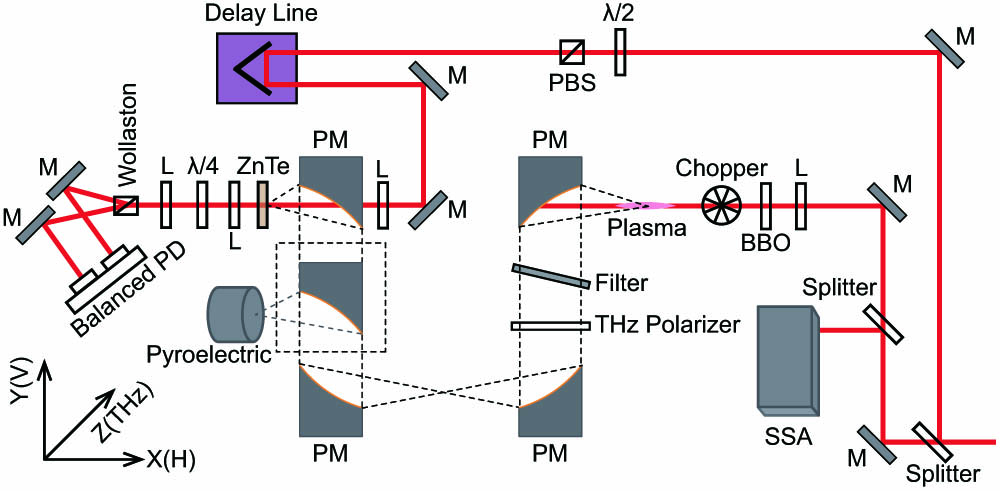
    Fig. 1. Experimental setup. The beam from the laser is split into two parts. The reflected part is used as a probe to detect THz with electro-optic sampling (EOS), and the other is used as a pump to generate THz. In the pump arm, another beam splitter is inserted to reflect part of the beam for monitoring the pulse width with SSA. The pump laser is focused by a lens. Between the lens and its focus, a BBO crystal is inserted. Transmitted FW and SH create two-color plasma, and THz is radiated. A PM collimates THz, and a second PM focuses THz. A third PM collimates THz again, and a fourth PM focuses THz for EOS. Between the third and fourth PMs, another PM mounted on a flip platform (PM in the dashed square) switches between THz electric field and power detections. The inset coordinate system shows the THz polarization and propagation directions. M, mirror; L, lens; PM, parabolic mirror; PD, photodiode; PBS, polarizing beam splitter; SSA, single shot autocorrelator.
    THz polarization characterized by a pyroelectric sensor and electro-optic sampling (EOS). (a) Power of THz transmitted through a THz polarizer versus the transmission axis angle β of the THz polarizer with respect to x axis. The power of THz is measured with a pyroelectric sensor. Red open circles denote experimental data, and the black curve is fit with Eq. (1). (b) Time-dependent horizontal (blue) and vertical (red) THz electric field with the three-dimensional (black) electric field and projected polarization trajectory (violet). THz electric field is measured with EOS.
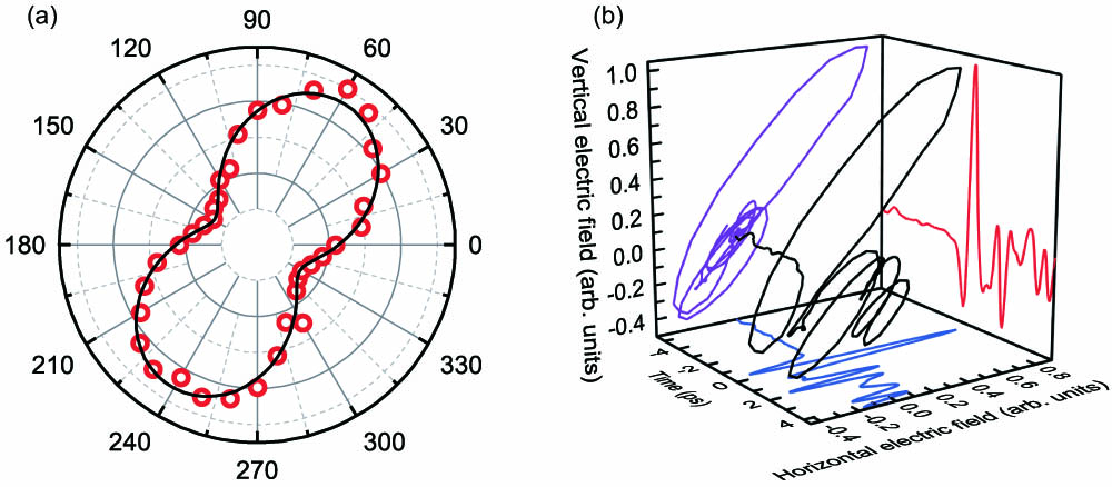
    Fig. 2. THz polarization characterized by a pyroelectric sensor and electro-optic sampling (EOS). (a) Power of THz transmitted through a THz polarizer versus the transmission axis angle β of the THz polarizer with respect to x axis. The power of THz is measured with a pyroelectric sensor. Red open circles denote experimental data, and the black curve is fit with Eq. (1). (b) Time-dependent horizontal (blue) and vertical (red) THz electric field with the three-dimensional (black) electric field and projected polarization trajectory (violet). THz electric field is measured with EOS.
    THz polarization variation with positive and negative chirps. The black arrows show the THz polarization rotation by looking into the increasing pulse width direction. The red arrows indicate the THz polarization rotation by looking into the increasing phase difference direction (see details in the text). The numbers near the curves are the pulse widths. (a) Polarization rotation for positively chirped pulses. (b) THz polarization rotation in the ∼50–78 fs range with a negative chirp. (c) THz polarization rotation in the ∼78–315 fs range with a negative chirp.
    Fig. 3. THz polarization variation with positive and negative chirps. The black arrows show the THz polarization rotation by looking into the increasing pulse width direction. The red arrows indicate the THz polarization rotation by looking into the increasing phase difference direction (see details in the text). The numbers near the curves are the pulse widths. (a) Polarization rotation for positively chirped pulses. (b) THz polarization rotation in the 5078  fs range with a negative chirp. (c) THz polarization rotation in the 78315  fs range with a negative chirp.
    THz intensity versus BBO-to-focus distance (BFD) with different laser chirps. The movement direction of the curves with pulse width is related to the initial phase difference φ0 (chirp-induced phase) between FW and SH. The dashed lines highlight the movement directions of the curves. Open circles and solid lines, respectively, indicate experimental and fitting results. The plots are vertically shifted for clarity. (a) THz intensity versus BFD when the laser is positively chirped. Curves constantly shift left with increasing pulse width from 50 to 445 fs. (b) THz intensity versus BFD when the laser is negatively chirped. The curves first move right when the pulse width increases from 50 to 80 fs and then shift left when the pulse width increases from 80 to 365 fs.
    Fig. 4. THz intensity versus BBO-to-focus distance (BFD) with different laser chirps. The movement direction of the curves with pulse width is related to the initial phase difference φ0 (chirp-induced phase) between FW and SH. The dashed lines highlight the movement directions of the curves. Open circles and solid lines, respectively, indicate experimental and fitting results. The plots are vertically shifted for clarity. (a) THz intensity versus BFD when the laser is positively chirped. Curves constantly shift left with increasing pulse width from 50 to 445 fs. (b) THz intensity versus BFD when the laser is negatively chirped. The curves first move right when the pulse width increases from 50 to 80 fs and then shift left when the pulse width increases from 80 to 365 fs.
    Initial phase difference φ0 (chirp-induced phase) and THz yield versus laser chirp. (a) Initial phase difference φ0 extracted by fitting the measured THz yield versus BBO-to-focus distance (BFD) with Eq. (3) as shown in Fig. 4. φ0 always increases with pulse width when the laser is positively chirped, whereas φ0 first decreases to a minimum and then increases with pulse width when the laser is negatively chirped. (b) THz yield versus laser chirp measured at BFD equal to 65 mm.
    Fig. 5. Initial phase difference φ0 (chirp-induced phase) and THz yield versus laser chirp. (a) Initial phase difference φ0 extracted by fitting the measured THz yield versus BBO-to-focus distance (BFD) with Eq. (3) as shown in Fig. 4. φ0 always increases with pulse width when the laser is positively chirped, whereas φ0 first decreases to a minimum and then increases with pulse width when the laser is negatively chirped. (b) THz yield versus laser chirp measured at BFD equal to 65 mm.
    THz polarization versus BBO-to-focus distance (BFD) at fixed laser chirps. The phase difference variation between FW and SH is realized by changing BFD for two typical positive and negative laser chirps. The left (right) column shows THz polarization trajectories and THz yield for pulse width equal to 110 (340) fs with a positive (negative) chirp. (a) and (c) THz polarization trajectories rotate clockwise (anticlockwise) with an increasing phase difference between FW and SH when the laser is positively (negatively) chirped. The arrows show the rotation directions. (b) and (d) THz yield versus BFD. The red open circles are experimental data. The black curves are fitting results with Eq. (3). The initial phase difference φ0 between FW and SH is obtained by fitting. Then the phase difference between FW and SH at each BFD is calculated with Eq. (2).
    Fig. 6. THz polarization versus BBO-to-focus distance (BFD) at fixed laser chirps. The phase difference variation between FW and SH is realized by changing BFD for two typical positive and negative laser chirps. The left (right) column shows THz polarization trajectories and THz yield for pulse width equal to 110 (340) fs with a positive (negative) chirp. (a) and (c) THz polarization trajectories rotate clockwise (anticlockwise) with an increasing phase difference between FW and SH when the laser is positively (negatively) chirped. The arrows show the rotation directions. (b) and (d) THz yield versus BFD. The red open circles are experimental data. The black curves are fitting results with Eq. (3). The initial phase difference φ0 between FW and SH is obtained by fitting. Then the phase difference between FW and SH at each BFD is calculated with Eq. (2).
    Sen Mou, Luca Tomarchio, Annalisa D’Arco, Marta Di Fabrizio, Salvatore Macis, Alessandro Curcio, Luigi Palumbo, Stefano Lupi, Massimo Petrarca. Impact of laser chirp on the polarization of terahertz from two-color plasma[J]. Photonics Research, 2023, 11(6): 978
    Download Citation