• Chinese Optics Letters
  • Vol. 21, Issue 3, 030603 (2023)
Yatian Li1、*, Tianwen Geng1, and Shijie Gao1、2
Author Affiliations
  • 1Changchun Institute of Optics, Fine Mechanics and Physics, Chinese Academy of Sciences, Changchun 130033, China
  • 2University of Chinese Academy of Sciences, Beijing 100049, China
  • show less
    DOI: 10.3788/COL202321.030603 Cite this Article Set citation alerts
    Yatian Li, Tianwen Geng, Shijie Gao. Improve the throughput of M-to-1 free-space optical systems by employing uniquely decodable codes[J]. Chinese Optics Letters, 2023, 21(3): 030603 Copy Citation Text show less

    Abstract

    This paper utilizes uniquely decodable codes (UDCs) in an M-to-1 free-space optical (FSO) system. Benefiting from UDCs’ nonorthogonal nature, the sum throughput is improved. We first prove that the uniquely decodable property still holds, even in optical fading channels. It is further discovered that the receiver can extract each source’s data from superimposed symbols with only one processing unit. According to theoretical analysis and simulation results, the throughput gain is up to the normalized UDC’s sum rate in high signal-to-noise ratio cases. An equivalent desktop experiment is also implemented to show the feasibility of the UDC-FSO structure.

    1. Introduction

    In the past decades, free-space optics (FSO) has attracted great attention as a promising solution for the “last mile” problem. The importance of FSO lies in its main advantages: low cost, high security, and freedom from spectral licensing issues[13]. With the deepening of research, it has gradually expanded from point-to-point links to the links involving multiple terminals, which can be viewed as the cooperative issue[4,5]. It is a common scenario where M terminals send information to one terminal, i.e., M-to-1 FSO systems[6].

    Although there are several suitable multiplexing methods for the M-to-1 FSO systems [such as wavelength division multiplexing (WDM), orbital angular momentum (OAM) multiplexing, polarization multiplexing, mode division multiplexing, and orthogonal frequency division multiplexing (OFDM)], the receiver needs multiple processing units, which is costly. When there is only one processing unit in the receiver, the data between the transceivers can still be effectively delivered with the help of time division multiplexing[7]. However, it brings no gains to the throughput. As a result, how to propose a high-throughput architecture without introducing other degrees of freedom is a problem worthy of study.

    With the development and application of 5G, researchers have proposed a sparse code division multiple access (SCMA) to improve throughput[8,9]. Unfortunately, the SCMA technique needs to combine high-dimensional quadrature amplitude modulation (QAM), which is not suitable for intensity modulation/direct detection (IM/DD) FSO systems. However, this inspired the authors to think that the nonorthogonal transmission might be combined with the FSO structure. Therefore, this paper integrates uniquely decodable codes (UDCs) and FSO organically to increase the sum throughput. In general, there are two main reasons for choosing UDC. First of all, since UDC is designed for adder channels[1012], the power superposition of intensity modulation is mathematically consistent with the code word superposition of UDC. Secondly, the nonorthogonal feature of UDC code words can further improve throughput. It should be noted that the nonorthogonal transmission of the UDC code domain is not a simple multilevel system. On the contrary, UDC can still construct a set of UDC code words in the multilevel space, such as the ternary space[13,14].

    In our previous work, we have studied the performance of UDC in a relay system with physical layer network coding (PNC) in radio frequency (RF) links[15,16]. However, there are two reasons why these studies cannot be applied to FSO links. First, FSO systems’ modulation methods are different from RF links, where the symbols in IM/DD FSO links cannot be divided into I-channels and Q-channels. [The subcarrier intensity modulation (SIM) is not considered in this paper.] Second, their channel fading models are different. It also needs to be mentioned that this paper is analyzed under “soft decision” circumstances, while the previous works only focus on the “hard decision” situations.

    In a word, this article studies an M-to-1 IM/DD FSO system, where there are M terminals transmitting information to a common receiving terminal simultaneously. Our aim is to improve the sum throughput. The main workload and innovations of this article are summarized as follows. This paper elaborates on a novel UDC-FSO structure in an M-to-1 FSO system, where the sum throughput is increased by the nonorthogonal feature of UDC.It is proved that the superimposed UDC code words still maintain the unique decodable (UD) characteristic even in optical fading channels, where the data from M terminals can be extracted with only one processing unit in the receiver.An equivalent desktop experiment is set up to show the feasibility of the proposed UDC-FSO structure, which indicates that UDC-FSO structure has the potential to be utilized in practical M-to-1 FSO systems.

    The system model is given in Section 2. We first prove the UD property can still be maintained in UDC-FSO systems in Section 3.1. The decision process and the throughput gain are illustrated in Section 3.2 and Section 3.3, respectively. The numerical results are shown in Section 4, with simulation results in Section 4.1 and experimental results in Section 4.2. Conclusions are drawn in Section 5. Also note that the variables are illustrated in lowercase italic forms. In addition, all the vectors in this paper are column vectors, which have the lowercase bold forms.

    2. System Model

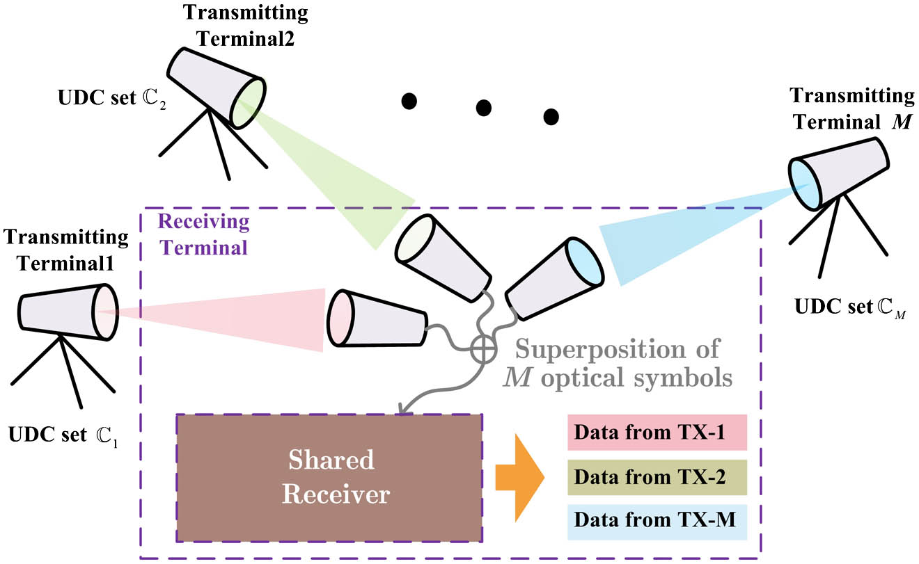
    This paper considers an M-to-1 IM/DD FSO system, where the UDC codes are employed, i.e., a UDC-FSO structure. According to Fig. 1, there are M terminals transmitting data to a common receiving terminal simultaneously. Suppose that Cm denotes the code set for the mth (1mM) transmitter. The length of any arbitrary code word in Cm is equal to n. During the transmission of the kth code word, the received signals are added by an optical coupler and the received photocurrent can be expressed as yk=ηm=1Mhmk·cmk+nk,where η stands for the photoelectric conversion ratio. nk represents the additive white Gaussian noise (AWGN) with zero mean and σn2 variance. cmkCm denotes the code word transmitted from the mth terminal. It is obvious that both yk and cmk are n tuple vectors, as well as nk. That is to say, it will take n time slots (TSs) to transmit any arbitrary kth code word. hmk denotes the corresponding channel gain. Considering both the turbulence fading and pointing error loss, the probability density function (PDF) obeys the Meijer’ G distribution[17], given in Eq. (2), fh(h)=αβρ2A0Γ(α)Γ(β)G1,33,0(αβhA0|ρ2ρ21,α1,β1),where α and β represent the effective number of large- and small-scale turbulent eddies, respectively. Γ() is the gamma function. A0 denotes the maximum fraction of the collected power in the receiving lens. ρ=wzeq/2σs represents the ratio between the equivalent beam radius wzeq and the standard deviation σs of the pointing errors.

    System structure of an M-to-1 UDC-FSO system.

    Figure 1.System structure of an M-to-1 UDC-FSO system.

    Thanks to the UD property, the receiver has the ability to extract transmitted data cmk(m=1,2,…,M) from received signal yk, which will be depicted in Section 3.

    3. Throughput Enhancement by UDC-FSO

    3.1. UD property in optical fading channels

    UDC is initially designed for the adder channel[10], where multiple information symbols from independent terminals are encoded and added into a single symbol. At the receiver, the decoder separates this coded symbol into the original symbols. Thereby, the coded symbols must possess a structural property such that they can be uniquely separated. The definition of UDC is furnished as follows. According to Ref. [10], C={Cm} can be defined as UDC sets, if and only if all the code words um,vmCm satisfy Eq. (3), m=1Mumm=1Mvm,where the set {um} is different from the set {vm}, i.e., {um}{vm}.

    The above uniquely decodable property in Eq. (3) can still hold after multiplying by positive weight {pm}, which is illustrated as Theorem 1. This indicates that the UDC can be efficient in optical fading channels.

    Theorem 1. For any arbitrary code words um and vm from the mth UDC set Cm satisfying {um}{vm}, the superimposed symbols can still remain uniquely decodable, i.e., m=1Mpm·vmm=1Mpm·um for positive {pm}.

    Theorem 1 will be proved with the help of both mathematical induction and the disproval method. During the proof, the variables {pm} are assumed to be positive.

    First, let us consider the case of M=2. Assume that there are code words u1,v1C1, u2,v2C2 ({v1,v2}{u1,u2}) satisfying p1·v1+p2·v2=p1·u1+p2·u2.

    This is equivalent to p1·w1+p2·w2=0, where wi denotes the subtraction of two vectors, ui and vi, i.e., wi=uivi. The vectors ui,wi,vi all have n tuple elements. We also assume wij (or uij, vij) stands for the jth (1jn) element of wi (or ui,vi). Because uij,vij{0,1}, we can get the elements of wi equal to ±1 or 0, i.e., wij{±1,0}. Recalling the assumption of p1·w1+p2·w2=0, Table 1 lists the value of p1·w1+p2·w2 in the cases of w1,j,w2,j{±1,0}.

    w1,j = 1w1,j = −1w1,j = 0
    w2,j = 1p1 + p2p1 + p2p2
    w2,j = −1p1p2p1p2p2
    w2,j = 0p2p20

    Table 1. Values of p1 · w1 + p2 · w2 versus w1,j, w2,j ∈ {±1, 0}

    Because p1,p2>0, there are only three possible zero candidates among the nine cases, which are p1p2, p1+p2, and w1,j=w2,j=0. The first two cases mean p1=p2. In this sequel, the assumption in Eq. (4) can degenerate into v1+v2=u1+u2, which contradicts the definition of UDC v1+v2u1+u2. So far, we have completed the proof of Theorem 1 in the case of M=2.

    According to the second step of mathematical induction, assume that we have proved Theorem 1 when Mt with any arbitrary integer t2, shown as m=1tpm·wm0.

    Let us discuss the results of M=t+1 in two cases: whether every wm,j (1mt+1,1jn) is equal to 0 or not. The first case will return to the situation of Mt. That is to say, the condition m=1t+1pm·wm0 is satisfied in the first case.

    In the second case, we will adopt the contradiction method again. Assume that m=1t+1pm·wm is equal to 0 for wmj{±1}. In this sequel, for any arbitrary j=j1, if we have the equation m=1t+1hm·wm,j1=0, we must ensure wm,j(jj1)=wm,j1 in order to have wm,j=wm,j1, i.e., wi{+1,1}. In other words, each UDC set Cm must contain code words of all zeros and all ones. However, this conflicts with the definition of UDC (m=1t+1umm=1t+1vm). We can give a counterexample, u1=1,u2=u3==ut+1=0, v2=1,v1=v3==vt+1=0.

    From the two cases above, it is proved that m=1t+1pm·wm0 is still satisfied under the circumstance of M=t+1.

    So far, Theorem 1 has been proved.

    3.2. Decision with single processing unit

    For ease of description, ΨC is defined as the sets of superimposed symbols after they pass through channels, i.e., ΨC={ηm=1Mhm·um,umCm}.

    Here are two examples of M=2 and M=3, where the set ΨC of superimposed symbols is given in Fig. 2. The UDC code sets are chosen from Ref. [16]. The UDC code sets for M=2 are C1={[0,0][1,1]} and C2={[0,1],[1,0],[0,0]}, respectively. It should be noted that the horizontal axis and the vertical axis refer to the first and second TS, respectively, rather than the I and Q channels. The UDC code sets for M=3 are C1={[0,0],[1,1]}, C2={[0,1],[1,0]}, and C3={[0,0],[1,0]}, respectively. In addition, it can also be seen intuitively from Fig. 2 that the superimposed code word still maintains the UD characteristic after the code words pass through the fading channel. It can be seen from Fig. 2 that the minimum Euclidean distances of the superimposed symbols are on the order of ηhm(m=1,2,…,M), which is the same order of magnitude as the Euclidean distance between symbols in point-to-point OOK links. In other words, we can conclude that the UDC-FSO system will be effective as long as channel conditions can ensure that all point-to-point links can work normally.

    Superimposed symbols for M = 2 and M = 3.

    Figure 2.Superimposed symbols for M = 2 and M = 3.

    We also define two operators, M[] and Mm[], to facilitate the relationship between UDC code words and superimposed symbols. The former represents the mapping between code words and superimposed symbols, i.e., ψj=M[{cm,j}m], while the latter denotes the reverse mapping for the mth transmitter, i.e., cm,j=Mm[ψj], where cm,j stands for the code word of the mth terminal corresponding to ψj. ψj denotes the jth (j=1,2,…,iCi) element of ΨC.

    The decoding process is depicted as follows. Due to the uniquely decodable feature, the decoding process consists of two steps, which are judging the superimposed symbols and demapping between the code words and superimposed symbols, respectively. For any arbitrary kth code word, φk(φkΨC) is defined to be the superimposed symbols. Without loss of generality, we may assume φk=ψj=M[{cm,j}m]. In this sequel, the soft decoding process is shown in Eqs. (6a) and (6b), respectively, φ^k=argminψpykψp2,p=1,2,…,ΨC,c^mk=Mm[φ^k],p=1,2,…,M.

    According to Theorem 1, it is known that in the absence of noise, the information of each transmitter can be extracted from the received superimposed symbols without errors, i.e., φ^k=ψj. Then the decoded code words c^mk are equal to cm,j. However, the original superimposed symbol φk=ψj may be judged a wrong symbol, i.e., φ^k=ψi(ψj), due to the presence of noise nk. In this sequel, the decoded code word is c^mk=cm,i. Different from the power domain NOMA technique, signals sent by different transmitters will not be considered as the interference items. All this is due to the UD property of UDC code words.

    3.3. Throughput and throughput gain

    For the convenience of comparison, the normalized throughput is defined as the number of symbols transmitted without error in a unit time. Then the normalized throughput TPUDC of the UDC-FSO scheme in Eq. (7), as well as the normalized throughput TPtrad of the traditional scheme, is given as TPUDC=m=1MRm·(1Ps,UDC),TPtrad=m=1Mρm(1Ps,m),where Ps,UDC is defined as the symbol error rate (SER) of a UDC-FSO system, shown as Ps,UDC=i=1ΨC1ΨCj=1,ijΨCPψiψj.

    Ps,m denotes the SER of the mth link in an M-to-1 system, where M terminals are used in turn with the utilization percentage ρm for the mth terminal, satisfying m=1Mρm=1. Rm denotes the rate of the mth UDC set, which can be obtained by the definition of entropy, Rm=1nlog2Cm, where denotes the number of elements in a vector .

    Substituting Eq. (8) into Eq. (7a), the throughput TPUDC is shown as Eq. (9), TPUDC=m=1MRm·[1i=1ΨC1ΨCj=1,ijΨCPψiψj].

    Next, we define the throughput gain GUDC introduced by UDC-FSO, which is GUDC=TPUDC/TPtrad.

    In order to show the performance of UDC-FSO in high SNR schemes, we define GUDC as the asymptotic throughput gain, given as GUDC=limSNRm=1MRm·(1Ps,UDC)/m=1Mρm=Rsum,where Rsum=m=1MRm represents the sum throughput.

    It can be indicated from Eq. (11) that the throughput gain GUDC of a UDC-FSO system approaches Rsum because the asymptotic limits of TPUDC and TPtrad are Rsum and 1, respectively. Taking the UDC sets mentioned above as examples, the asymptotic throughput gain GUDC is equal to Rsum=0.5×(log23+log22)=1.29 for the M=2 case, while GUDC is equal to 1.5 for the M=3 case, which will be further verified in Section 4.

    According to information theory[18], the throughput of M users’ nonorthogonal multiple access must satisfy {0RiH1:1iM0Ri+RjH2:1ijM0R1+R2++RMHM,where Hm=i=0m12m(mi)(mlog2(mi)) denotes the throughput bound for m users. In other words, HM is the upper bound of asymptotic throughput gain GUDC for M transmitting terminals. However, how to design the UDC sets to make the sum throughput close to the bound HM is also one of the topics to be studied in the future.

    4. Numerical Results

    In this section, the simulation results are given in Section 4.1. Section 4.2 will depict the setup of the experiment and corresponding experimental results, which verify the feasibility of applying UDC to FSO systems.

    4.1. Simulation results

    In this subsection, the numerical results of both error performance and throughput are furnished. During the simulation, the effective number of large- and small-scale turbulent eddies is set as α=5.977 and β=4.398. The receiving lens’s radius is assumed to be 10 cm. Equivalent beam radius wzeq and standard deviation σs pointing errors are set to be 2.5021 m and 0.2 m, respectively. The responsivity of the detector is 0.9. Figure 3 illustrates the error performance of M=2 and M=3. As can be seen from Fig. 3, the error performance of UDC-FSO is worse than that of the scheme without UDC, which occurs because the minimum distance of superimposed symbols is smaller than in the schemes without UDC. However, the scheme will still benefit from the UDC having larger throughput in high SNR regimes. In other words, the UDC-FSO system sacrifices reliability for effectiveness, which can be seen from Fig. 4.

    Error performance of UDC-FSO systems with M = 2 and M = 3.

    Figure 3.Error performance of UDC-FSO systems with M = 2 and M = 3.

    Throughput performance of FSO-UDC systems for M = 2 and M = 3.

    Figure 4.Throughput performance of FSO-UDC systems for M = 2 and M = 3.

    Figure 4 compares the throughput of UDC-FSO systems and traditional M-to-1 FSO systems, where the throughput gain GUDC is also given. It can be seen that TPUDC is larger than TPtrad in large SNR cases (i.e., SNR>8.24dB for M=2, SNR>12.01dB for M=3), which is due to the nonorthogonal characteristics of UDC. In other words, more data can be correctly transmitted in every unit time slot. It also means that TPUDC approaches the Rsum in a high SNR scheme, while TPtrad approaches 1.

    There is a trade-off between the error performance and throughput, since the UDC-FSO’s influence on the throughput can be viewed as a confrontation between the advantage of the freedom gain brought by UDC and the disadvantage of increasing transmission errors caused by reducing the Euclidean distance of the superimposed signals. As obtained from both Figs. 3 and 4, there are more errors happening in the case of a small SNR, which constrains the increase of the throughput, even though more data are transmitted in the UDC-FSO system. However, in large SNR schemes, the throughput improvement of the UDC-FSO system is due to the nonorthogonal characteristic brought by UDC, where the above-mentioned disadvantage can be ignored. The throughput improvement can be achieved by extracting the data from M terminals without an extra processing unit in the receiver, whose cost is acceptable.

    4.2. Experimental results

    In order to verify the feasibility of the proposed UDC-FSO structure, we implemented an equivalent experiment with M=2 as an example. The block diagram of the experiment is shown in Fig. 5. The data after UDC encoding with C1={[0,0],[1,1]} and C2={[0,1],[1,0],[0,0]} are generated by two channels of an arbitrary wave generator (AWG, Tektronix 70002A). The two channels of the AWG share the same reference clock in order to let the code words be superimposed synchronously. The role of the amplifiers is to match the signal to the Mach–Zehnder (MZM) modulator’s (Ixblue DR-DG-10-MO-NRZ) voltage vπ. The two modulated optical signals need to pass through their respective attenuators before reaching the lens. Attenuator 1 and attenuator 2 simulate the channel gains (h1 and h2), respectively.

    Block diagram of the experiment.

    Figure 5.Block diagram of the experiment.

    As shown in Fig. 5, the beams emitted by the two transmitting lenses are joined together by a beam splitter with the splitting ratio of 50:50. The blue beam is transmitted directly through the beam splitter, while the red beam is reflected from the beam splitter and reaches the receiving lens. It should be noted that the two optical paths need to be kept equidistant to avoid asynchronous superposition. It needs to be mentioned that it is not necessary to ensure that the distances of each link are strictly equal in actual scenarios. The delay of each transmitter can be dynamically adjusted to ensure that the optical path difference of each link is an integral multiple of the UDC code word length, which further ensures that UDC code words passing through channels are superimposed synchronously in the receiver. The received optical signals are converted into a current signal by the avalanche photodiode (APD, η0.95), which are further turned into voltage signals with the help of the transimpedance amplifier (TIA). The amplified electrical signal is finally collected by an oscilloscope (Tektronix DPO73304D). The values of the two above-mentioned attenuators are adjusted; the cases of h1<h2 and h1>h2 are given in Figs. 6(a) and 6(b), respectively.

    Experimental verification of 2 × 1 UDC-FSO with C1={[0,0],[1,1]} and C2={[0,1],[1,0],[0,0]}.

    Figure 6.Experimental verification of 2 × 1 UDC-FSO with C1={[0,0],[1,1]} and C2={[0,1],[1,0],[0,0]}.

    As can be seen in Fig. 6, the circumstances of cases h1<h2 and h1>h2 will result in different superimposed symbols, as well as different Euclidean distances, as analyzed in Section 4. What is more, the superimposed code words still remain uniquely decodable, where the color of each label in Fig. 6 is consistent with the points in Fig. 2. This verifies Theorem 1.

    As mentioned above, the system performance depends on Euclidean distance. Therefore, we show cumulatively the superimposed symbols before and after the exchange of h1 and h2 in Figs. 7(a) and 7(b), where the ratio of channel gains is about 2.91, i.e., h1/h22.91 in Fig. 7(a) and h2/h12.91 in Fig. 7(b). It can be seen from Fig. 7 that the minimum Euclidean distance between superimposed symbols in the first case is smaller than that in the second case, which means that the error performance of the former case is worse. The experimental results also prove this point, where the SERs are 6.12 × 10−3 and 1.036 × 10−4, respectively. The corresponding throughputs are 1.2821 and 1.2899, which both approach GUDC=Rsum=1.29. So far, we can conclude that the proposed UDC-FSO scheme is feasible and has the potential to be applied in actual systems.

    Cumulative superimposed symbols before and after the exchange of h1 and h2.

    Figure 7.Cumulative superimposed symbols before and after the exchange of h1 and h2.

    The above analysis gives us hints on how to further improve the performance of UDC-FSO systems. (1) Improve the minimum Euclidean distance by designing excellent UDC code words. (2) If the transmitters have the knowledge of channel gains, the minimum Euclidean distance can be increased by power allocation or code word set selection, which will be the follow-up work.

    5. Conclusion

    This paper proposes a UDC-FSO structure for an M-to-1 system to enhance the throughput. It is proved that the superimposed UDC symbols after optical fading channels can remain uniquely decodable, so that the receiver can distinguish the data from different sources. We have also deduced the expressions of SER and throughput. Despite the fact that the error performance of UDC-FSO is worse than the scheme without UDC, the former’s throughput outperforms the latter’s in the high SNR cases. What is more, benefiting from the nonorthogonal characteristics of UDC, the former’s normalized throughput asymptotically approaches the sum rate of UDC sets (larger than 1) with sufficient SNR. However, the latter’s normalized throughput cannot exceed 1. In addition, an equivalent desktop experiment is also set up to show the feasibility of the proposed UDC-FSO structure, which indicates that the proposed UDC-FSO structure has the potential to be utilized in practical M-to-1 systems.

    References

    [1] A. Al-Kinani, C. Wang, L. Zhou, W. Zhang. Optical wireless communication channel measurements and models. IEEE Commun. Surveys Tuts., 20, 1939(2018).

    [2] L. Zhao, Y. Hao, L. Chen, W. Liu, M. Jin, Y. Wu, J. Tao, K. Jie, H. Liu. High-accuracy mode recognition method in orbital angular momentum optical communication system. Chin. Opt. Lett., 20, 020601(2022).

    [3] J. Zhong, J. Zhou, S. Gao, W. Liu. Secure orthogonal time-frequency multiplexing with two-dimensional encryption for optical-wireless communications. Chin. Opt. Lett., 19, 050603(2021).

    [4] F. Xing, H. Yin, X. Ji, V. Leung. Joint relay selection and power allocation for underwater cooperative optical wireless networks. IEEE Trans. Wireless Commun., 19, 251(2020).

    [5] Z. Cao, X. Zhang, G. Osnabrugge, J. Li, I. M. Vellekoop, A. M. J. Koonen. Reconfigurable beam system for non-line-of-sight free-space optical communication. Light Sci. Appl., 8, 591(2019).

    [6] A. Ghazy, H. Selmy, H. M. Shalaby. Fair resource allocation schemes for cooperative dynamic free-space optical networks. J. Opt. Commun. Netw., 8, 822(2016).

    [7] J. Liu, J. Sando, S. Shimamoto, C. Fujikawa, K. Kodate. Experiment on space and time division multiple access scheme over free space optical communication. IEEE Trans. Consum. Electron., 57, 1571(2011).

    [8] M. Moltafet, N. Yamchi, M. Javan, P. Azmi. Comparison study between PD-NOMA and SCMA. IEEE Trans. Veh. Technol., 67, 1830(2018).

    [9] W. Yuan, N. Wu, Q. Guo, Y. Li, C. Xing, J. Kuang. Iterative receivers for downlink MIMO-SCMA: message passing and distributed cooperative detection. IEEE Trans. Wireless Commun., 17, 3444(2018).

    [10] T. Kasami, S. Lin, V. Wei, S. Yamamura. Graph theoretic approaches to the code construction for the two-user multiple- access binary adder channel. IEEE Trans. Inf. Theory, 29, 114(1983).

    [11] S. Lu, W. Hou, J. Cheng, H. Kamabe. Multi-user UD k-ary codes recursively constructed from short-length multiary codes for multiple-access adder channel. IEEE International Symposium on Information Theory, 425(2019).

    [12] A. Singh. Set of uniquely decodable codes for overloaded synchronous CDMA. IET Commun., 10, 1236(2016).

    [13] S. Lu, W. Hou, J. Cheng, H. Kamabe. A new kind of nonbinary uniquely decodable codes with arbitrary code length for multiple-access adder channel. IEEE Information Theory Workshop, 1(2018).

    [14] M. Kulhandjian, C. Amours, H. Kulhandjian. Uniquely decodable ternary codes for synchronous CDMA systems(2018).

    [15] Y. Li, Q. Yu, K. He, W. Xiang. Apply uniquely-decodable codes to multiuser physical-layer network coding based on amplify-and-forward criterion. IEEE Global Communications Conference, 1(2015).

    [16] Q. Yu, Y. Li, W. Meng, W. Xiang. Uniquely decodable codes for physical-layer network coding in wireless cooperative communications. IEEE Syst. J., 13, 3956(2019).

    [17] M. Uysal, C. Capsoni, Z. Ghassemlooy, A. Boucouvalas, E. Udvary. Optical Wireless Communications(2016).

    [18] T. M. Cover, J. A. Thomas. Elements of Information Theory(2006).

    Yatian Li, Tianwen Geng, Shijie Gao. Improve the throughput of M-to-1 free-space optical systems by employing uniquely decodable codes[J]. Chinese Optics Letters, 2023, 21(3): 030603
    Download Citation