Myungjin Cho, Donghak Shin. 3D image reconstruction with a controllable overlapping number of elemental images in computational integral imaging[J]. Chinese Optics Letters, 2015, 13(5): 051101
Copy Citation Text
In this Letter, we propose a three-dimensional (3D) image reconstruction method with a controllable overlapping number of elemental images in computational integral imaging. The proposed method can control the overlapping number of pixels coming from the elemental images by using the subpixel distance based on ray optics between a 3D object and an image sensor. The use of a controllable overlapping number enables us to provide an improved 3D image visualization by controlling the inter-pixel interference within the reconstructed pixels. To find the optimal overlapping number, we simulate the pickup and reconstruction processes and utilize the numerical reconstruction results using a peak signal-to-noise ratio (PSNR) metric. To demonstrate the feasibility of our work in optical experiments, we carry out the preliminary experiments and present the results.
Integral imaging (II) has been considered for the promising three-dimensional (3D) display technique due to its several advantages, including full parallax, the continuous viewing angle, and its full color display, which can be seen without the need for special viewing glasses[1–4]. The general II system consists of a pickup part and a reconstruction part. In the pickup part, rays coming from a 3D object are captured by an image sensor and a lenslet array. Here, the captured ray image is called an elemental image. The 3D image can be reproduced in the reconstruction part. Up until now, only two different kinds of reconstruction methods have been studied: optical reconstruction[5–9] and computational integral imaging reconstruction (CIIR)[10–18]. During the optical reconstruction for 3D display, 3D images are optically reconstructed using a lenslet array and a display panel. However, it has some problems, which are caused by the physical limitations of optical devices, such as diffraction and aberration. To overcome these challenges, a CIIR method based on a virtual pinhole array model has been studied for many useful applications, such as 3D object visualization, recognition, tracking, and so on[10–18].
Even though the CIIR method can provide the effectively volumetric 3D information, it has some serious problems with the artifacts of the reconstructed images, the high computational load, and undesired image blurring. Among them, the image blurring may result in the serious degradation of the 3D reconstructed image. This image blurring originates from the inter-pixel interference among the adjacent magnified pixels in the overlapping process of the CIIR method[12]. Recently, several studies have worked to overcome this inter-pixel interference problem. In 2008, a CIIR algorithm with scale-variant magnification, in which the minimum magnification factor was used to reduce the inter-pixel interference, was proposed[12]. In 2012, a CIIR method based on subpixel optical ray sensing, in which the pixel with the minimum subpixel distance is used to generate 3D images instead of the overlapping processing, was reported[18]. However, this method may produce incorrect images under the noise environment, due to the single pixel extraction.
In this Letter, we propose a new CIIR method with a controllable overlapping number of elemental images. In the proposed method, we can control the overlapping number of pixels coming from the elemental images. It is based on the calculation of the subpixel distance based on ray optics between a 3D object and an image sensor. Due to the control of the inter-pixel interference, the overlapping number of elemental images is related to the visual quality of the reconstructed images. We find the optimal overlapping number using the computational framework of the pickup and reconstruction processes. After that, we can apply the optimal overlapping number to optical experiments involving 3D image reconstruction.
Sign up for Chinese Optics Letters TOC. Get the latest issue of Chinese Optics Letters delivered right to you!Sign up now
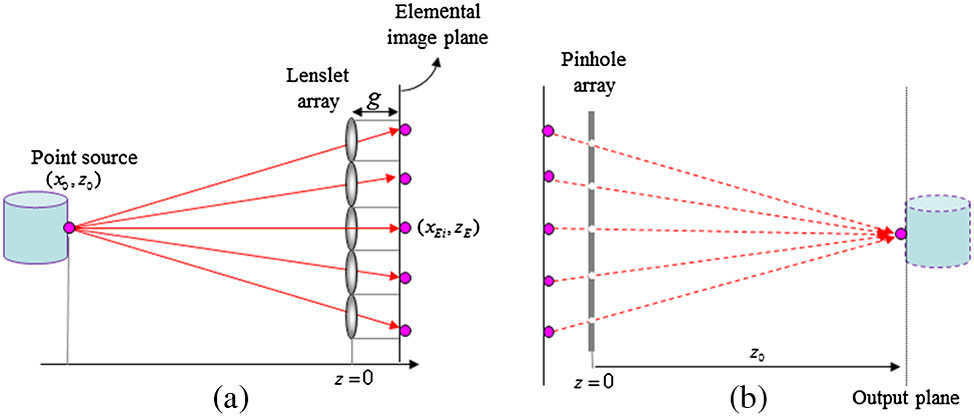
Before explaining the proposed CIIR method, we present the principle of the overlapping process in CIIR. For illustration purposes, we assume that a single point source is the object. A typical II system with CIIR is shown in Fig. 1. In the pickup part, as shown in Fig. 1(a), the rays coming from a point source are recorded through the lenslet array into the elemental images. Each elemental image is of the different direction and intensity information of the 3D object. After the recording process, the elemental images are used in the CIIR process. Here, the virtual pinhole array is used instead of the lenslet array to reconstruct the 3D images. With the elemental images for a single point source, as shown in Fig. 1(b), the plane image is reconstructed at the original distance where the point source was located by properly back-propagating the rays from the elemental images. Then, we can reconstruct the point image by overlapping the inversely projected rays onto the reconstruction plane (). The output pixel intensity of the point image in the reconstruction plane is calculated by averaging all of the integrated ray intensities. However, the typical image sensor is pixelated with the pixel size. Therefore, it is impossible to reproduce the perfectly integrated point source, as shown in Fig. 1(b). Based on this fact, we can obtain the subpixel distance using the ray relationship between the point object and the elemental images, as described in the previously reported CIIR method[18].
Figure 1.Computational II. (a) Pickup. (b) Reconstruction.
The principle of the proposed CIIR method is illustrated in Fig. 2. Here, the relationship between the -th sensor and the object space is considered. A point source is located at an arbitrary position in the object space. In the reconstruction process, the single point source can be considered as a pixel in the reconstructed plane. The point source is recorded into a specific discrete pixel of the image sensor. The mapping point of the ray may be far from the pixel center, as shown in Fig. 2. In the proposed framework, we try to use the distance between the mapping point and the center of the corresponding pixel as the decision parameter. This is referred to as the subpixel distance. For the sake of simplicity, a one-dimensional notation is used. As shown in Fig. 2, it is assumed that the -th lenslet is located at . The focal length and diameter of the lenslet are and , respectively. When a point source is located at , a point source is recorded into -th elemental image. The position of recorded point source is given by
Figure 2.Ray diagram between the object point and the elemental image.
Now, we consider the pixilation process in the image sensor. The integer index of the discrete pixel used to record the point source is given by where is the pixel size and is the rounding operation.
Then, we define the sub-pixel distance between the pixel center and the position of the recorded point source as
It is seen that has different values according to the corresponding lenslet. Therefore, we can see that the point source is more precisely mapped when the distance is smaller.
Sign up for Chinese Optics Letters TOC. Get the latest issue of Chinese Optics Letters delivered right to you!Sign up now
After calculating all values for all lenslets, the values are sorted from lowest to highest. We also store the position values and intensities of the corresponding lenslet for all values together. They can be represented by
Here, and represent the sorted position values and intensities for all values, respectively. Among them, we can select the proper overlapping number () for the low values according to the visual quality of the reconstructed 3D images. For example, we can select lenslets among lenslets. In fact, the proposed method can be considered to be the generalized version of the CIIR method, based on the quality of the reconstructed image. That is, the same image reconstructed from the original CIIR method[10] is obtained when . The CIIR method with the minimum subpixel distance is implemented when .
For the selected lenslet ( to ), the reconstructed image at the distance can be obtained by calculating the average intensity of the projected pixels. This is given by
Figure 3 shows an example of the reconstruction process when and . The reconstructed point image is calculated by averaging the intensities of and .
Figure 3.Principle of computational reconstruction in the proposed method.
To show the usefulness of the proposed method, we have performed two experiments. The purpose of the first experiment is to find the optimal overlapping number by using some two-dimensional (2D) plane images for the computational framework of the pickup and reconstruction processes. In the second experiment, we reconstruct 3D images using the proposed CIIR method with the optimal overlapping number.
First, to find the optimal overlapping number for the proposed CIIR method, we design a framework that has a computational pickup and a CIIR process. We use a 2D plane image. The framework is shown in Fig. 4(a). In the pickup process, we suppose a 2D plane image be located at the distance . The pinhole array used in this experimental setup is composed of pinholes and is located at . The interval between the pinholes is 1.08 mm, and the gap between the elemental images and the pinhole array is 3 mm. Then, 2D elemental images with pixels are computed by a computational pickup when the 2D plane image is located at the distance . The distance of the reconstruction plane was changed from 24 to 45 mm with a step of 1.5 mm. Next, the recorded 2D elemental images are used in the proposed framework of the CIIR process. According to the principle of our CIIR method as described in earlier explanation, we reconstruct 3D images at different reconstruction planes.
Figure 4.(a) The framework with a computational pickup and a CIIR process using a 2D plane image. (b) Ten test images. (c) Graph of the averaged PSNR values.
To objectively evaluate the quality of a reconstructed image , we calculate the peak signal-to-noise ratio (PSNR), which is defined as
Figure 4(b) shows the ten test images used in the computational experiments. After calculating the PSNR values for the test images and the distance range from 24 to 45 mm, the average PSNR value is obtained and presented in Fig. 4(c). It is seen that the maximum peak of the PSNR can be obtained when . This means that the -value CIIR method can provide the better-reconstructed images compared with the conventional subpixel method () and the original method ().
Next, we performed optical experiments using the calculated optimal overlapping number. Figure 5(a) shows the experimental setup for recording elemental images. Here, the 3D objects we used are a “car1” object and “car2” object. They are positioned approximately 350 and 430 mm away from the lenslet array, respectively. To record the elemental images without distortion, we used the synthetic aperture II method where a camera was moved with a step of 2 mm. Then, we obtained elemental images with a low resolution, as shown in Fig. 5(b). Each elemental image has pixels. Figure 5(c) shows an example of the recorded elemental images with low resolution.
Figure 5.(a) Experimental condition. (b) The recorded elemental images. (c) Enlarged “car1” image among elemental images.
With elemental images, we reconstructed the 3D images using the proposed method. The “car1” object and “car2” object were reconstructed at their original positions. Figure 6 shows the results of the reconstructed image for the “car1” objects using the three different values (, 3, and 100). was optimal overlapping number, as calculated in the previous numerical experiment. Here, the case of is equal to the original CIIR method in Ref. [10], and the case of is the same as the subpixel CIIR method used in Ref. [18]. The “car1” object was focused at , as shown in Fig. 6. Figure 7 is the reconstructed image for the “car2” object. The “car2” object was focused at .
Figure 6.Reconstructed image at where the “car1” object was originally located. (a) case with the best visual quality. (b) case (original CIIR method). (c) case (subpixel-based CIIR method).
Figure 7.Reconstructed image at where the “car2” object was originally located. (a) case with best visual quality. (b) case (original CIIR method). (c) case (subpixel-based CIIR method).
As shown in Figs. 6(b) and 7(b), the case of (the original CIIR method) generated the reconstructed images that had the blurriest pixels. The reconstructed images with the roughest pixels were observed when (the subpixel-based CIIR method), as shown in Figs. 6(c) and 7(c). The case when provided the best image quality of the reconstructed images, as shown in Figs. 6(a) and 7(a). From the results of Figs. 6 and 7, we can see that the proposed method with a controllable overlapping number of elemental images can improve the visual quality of the reconstructed images compared with the conventional methods.
In conclusion, we propose a generalized version of the CIIR method with a controllable overlapping number of elemental images. In this method, we find the optimal overlapping number through the numerical experiments using 2D plane images, and then reconstruct the 3D images using the CIIR method with the optimal overlapping number of pixels coming from the elemental images. The experimental results reveal that the proposed method with optimal overlapping number of elemental images can improve the visual quality of the reconstructed images compared with the conventional methods.
Myungjin Cho, Donghak Shin. 3D image reconstruction with a controllable overlapping number of elemental images in computational integral imaging[J]. Chinese Optics Letters, 2015, 13(5): 051101