
Lixin Yuan, Yu Cai, Yuxi Chu, Jintao Fan, Minglie Hu. Generation of sub-three-cycle pulses at 53 MHz repetition rate via nonlinear compression in optical parametric oscillator[J]. Chinese Optics Letters, 2022, 20(5): 051901
- Chinese Optics Letters
- Vol. 20, Issue 5, 051901 (2022)
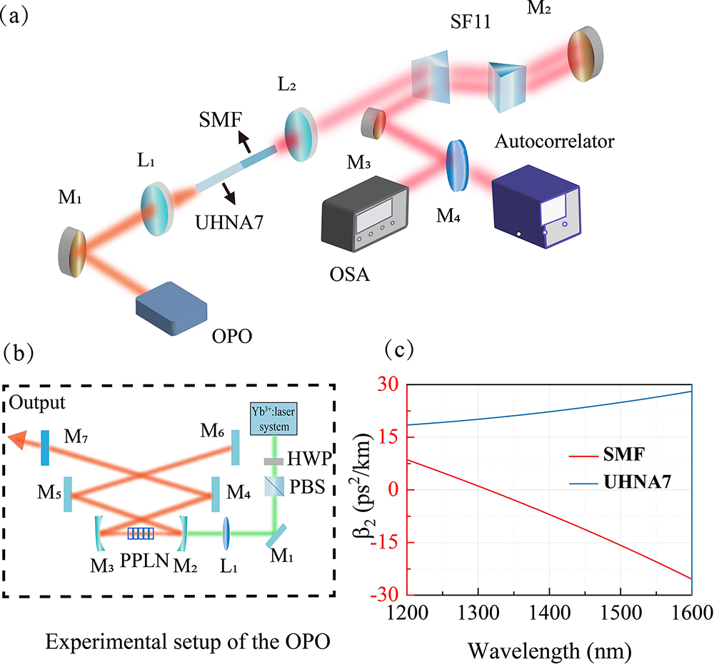
Fig. 1. (a) Schematic diagram of the experimental setup. M, mirrors; L, lenses; SF11, Brewster-angled prism pulse compressor; OSA, optical spectrum analyzer. (b) Experimental setup of the OPO. HWP, half-wave plate; PBS, polarizing beam splitter; M1, M4–M7, mirrors; M2, M3, lenses; PPLN, periodically poled lithium niobate crystal. (c) The GVD (β2) profile of UHNA7 and SMF.
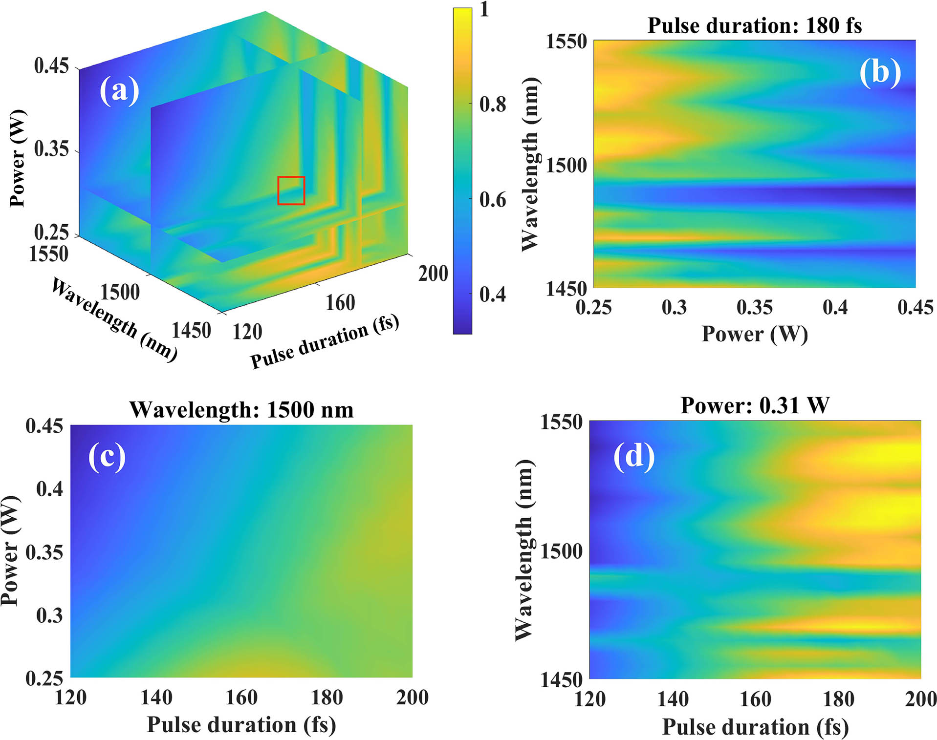
Fig. 2. (a) Simulation of SR for different wavelengths, pulse durations, and powers. (b)–(d) Slice diagrams of (a) with pulse duration of 180 fs, central wavelength of 1500 nm, and power of 0.31 W, respectively. The color bar represents the SR.
Fig. 3. (a) Output spectrum from the OPO. (b) Typical intensity autocorrelation trace at 1502 nm.
Fig. 4. (a) Experimental and simulated final output spectra at 1502 nm. (b) Simulation of spectral evolution in 27 cm UHNA7 and 15 cm SMF.
Fig. 5. (a) Interferometric autocorrelation of pulses at 1502 nm; AC signal, autocorrelation signal. (b) Temporal intensity envelope and phase at 1502 nm. (c) Central wavelength and spectral bandwidth (at −10 dB) stability at 1502 nm over a period of 20 min. The inset shows spectral stability measurement over the same period.
Fig. 6. (a) Ultrabroad spectrum after the UHNA7 fiber and seed spectrum. (b) Interferometric autocorrelation of the pulses at 1463 nm after OPO adjustment. (c) Temporal intensity envelope and phase at 1463 nm after OPO adjustment.

Set citation alerts for the article
Please enter your email address
© Copyright 2018-2021 | Chinese Laser Press. All Rights Reserved 沪ICP备15018463号-20