
Yi Liu, Si-Zhong Hao, Yu-Lin Tian, Guo-Zhong Liu. Two-dimensional phase sensitive detector and its application to demodulating amplitude modulated image [J]. Acta Physica Sinica, 2019, 68(22): 224204-1
- Acta Physica Sinica
- Vol. 68, Issue 22, 224204-1 (2019)
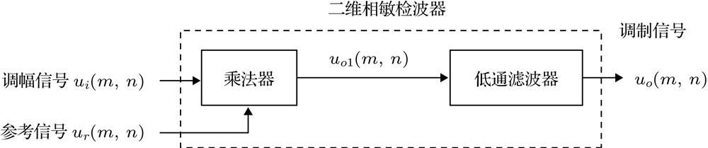
Fig. 1. Block diagram of 2D PSD.二维相敏检波器组成
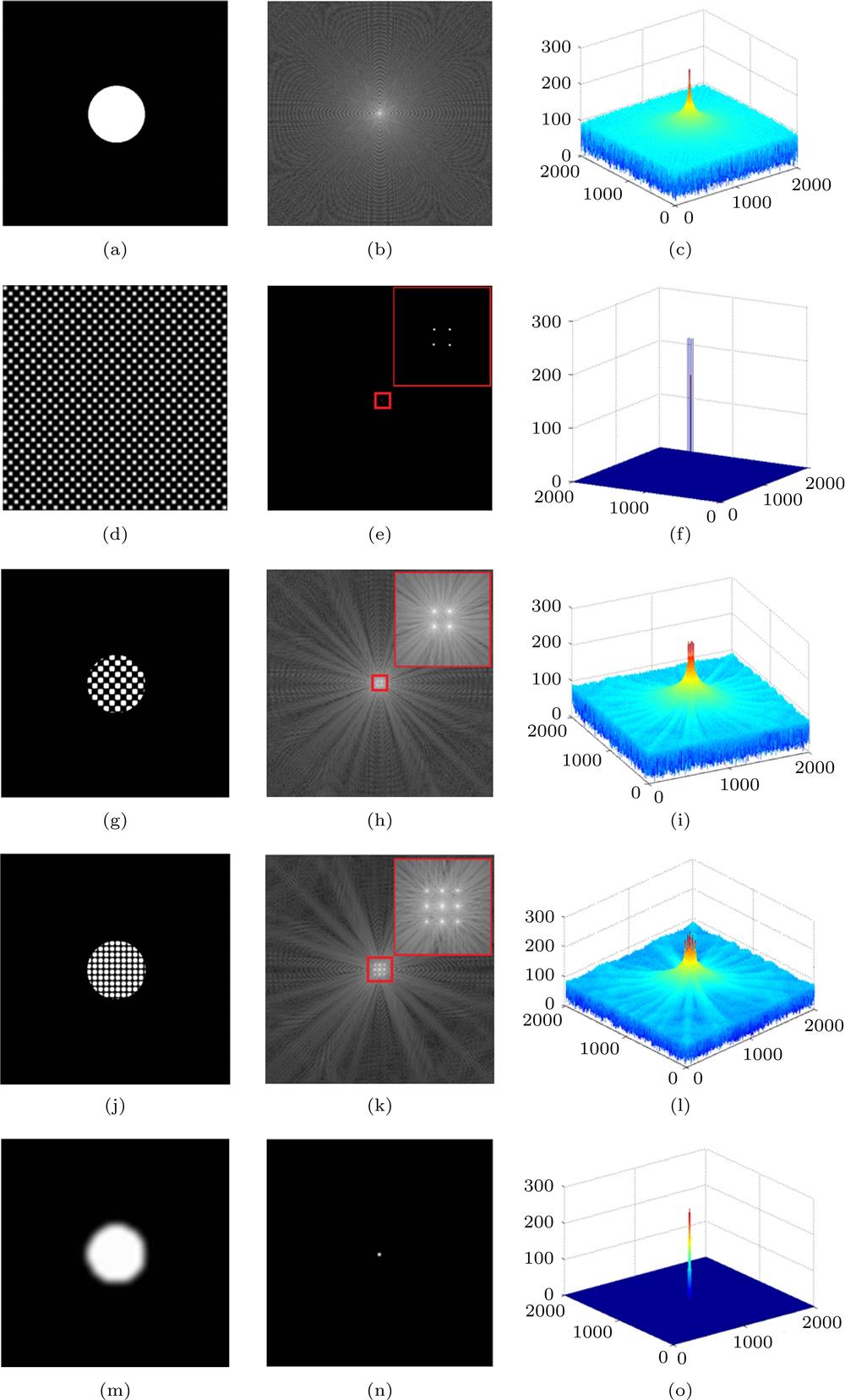
Fig. 2. Simulation of 2D spatial modulation and 2D PSD: (a) Spatial image of 2-D modulating signal; (b) frequency domain image of 2D modulating signal; (c) frequency domain 3D mesh image of 2D modulating signal; (d) spatial image of 2D carrier signal; (e) frequency domain image of 2D carrier signal; (f) frequency domain 3D mesh image of 2D carrier signal; (g) spatial image of 2D modulated signal; (h) frequency domain image of 2D modulated signal; (i) frequency domain 3D mesh image of 2D modulated signal; (j) output spatial image of multiplier; (k) output frequency domain image of multiplier; (l) output frequency domain 3D mesh image of multiplier; (m) output spatial image of 2D PSD; (n) output frequency domain image of 2D PSD; (o) output frequency domain 3D mesh image of 2D PSD.二维空间调制及二维相敏检波过程 (a) 二维调制信号空域图像; (b) 二维调制信号频域2D图像; (c) 二维调制信号频域3D网格图像; (d) 二维载波信号空域图像; (e) 二维载波信号频域2D图像; (f) 二维载波信号频域3D网格显示; (g) 二维调幅信号空域图像; (h) 二维调幅信号频域2D图像; (i) 二维调幅信号频域3D网格图像; (j) 乘法器输出信号空域图像; (k) 乘法器输出信号频域2D图像; (l) 乘法器输出信号频域3D网格图像; (m) 相敏检波器输出信号空域图像; (n) 相敏检波器输出信号频域2D图像; (o) 相敏检波器输出信号频域3D网格图像
Fig. 3. Simulation flow of demodulation and noise suppression of two different demodulation methods: (a) Rectifier + filtering method; (b) 2D PSD.两种不同检波器检波方法及噪声抑制特性仿真流程 (a) 整流滤波方法; (b) 二维相敏检波方法
Fig. 4. Noise suppression characteristics of two demodulation methods in different noise background: (a) Amplitude-modulated signal of 60 dB; (b) output spatial image of 2D PSD in case of 60 dB; (c) output spatial domain 3D mesh image of 2D PSD in case of 60 dB; (d) output spatial image of rectifier + filtering method in case of 60 dB; (e) output spatial domain 3D mesh image of rectifier + filtering method in case of 60 dB; (f) amplitude-modulated signal of 0 dB; (g) output spatial image of 2D PSD in case of 0 dB; (h) output spatial domain 3D mesh image of 2D PSD in case of 0 dB; (i) output spatial image of rectifier + filtering method in case of 0 dB; (j) output spatial domain 3D mesh image of rectifier + filtering method in case of 0 dB; (k) amplitude-modulated signal of –30 dB; (l) output spatial image of 2D PSD in case of –30 dB; (m) output spatial domain 3D mesh image of 2D PSD in case of –30 dB; (n) output spatial image of rectifier + filtering method in case of –30 dB; (o) output spatial domain 3D mesh image of rectifier + filtering method in case of –30 dB.二维调幅信号在加入不同噪声情况下两种检波方法噪声抑制特性 (a) 信噪比60 dB调幅信号; (b) 输入60 dB, 二维相敏检波输出空域2D图像; (c) 输入60 dB, 二维相敏检波输出空域3D网格图像; (d) 输入60 dB, 整流 + 滤波方法输出空域2D图像; (e) 输入60 dB, 整流 + 滤波方法输出空域3D网格图像; (f) 信噪比0 dB调幅信号; (g) 输入0 dB, 二维相敏检波输出空域2D图像; (h) 输入0 dB, 二维相敏检波输出空域3D网格图像; (i) 输入0 dB, 整流 + 滤波方法输出空域2D图像; (j) 输入0 dB, 整流 + 滤波方法输出空域3D网格图像; (k) 信噪比–30 dB调幅信号; (l) 输入–30 dB, 二维相敏检波输出空域2D图像; (m) 输入–30 dB, 二维相敏检波输出空域3D网格图像; (n) 输入–30 dB, 整流 + 滤波方法输出空域2D图像; (o) 输入–30 dB, 整流 + 滤波方法输出空域3D网格图像
Fig. 5. Variation curve of output signal-to-noise ratio with input signal-to-noise ratio for two demodulation methods.两种不同检波方法输出信噪比随输入信噪比的变化
Fig. 6. Typical defect images of shielding glass: (a) Black spot; (b) scratch; (c) white line.屏蔽玻璃典型缺陷图像 (a) 黑点; (b) 划痕; (c) 白线
Fig. 7. Flow chart of defect detection algorithm for shielding glass: (a) Direct filtering method; (b) rectifier + filtering method; (c) 2D PSD(extracting carrier approximately); (d) 2D PSD(extracting carrier accurately).屏蔽玻璃缺陷检测算法流程 (a) 直接滤波方法; (b) 整流 + 滤波方法; (b) 二维相敏检波方法之一(近似提取载波); (d) 二维相敏检波方法之二(精确提取载波)
Fig. 8. Detection process of defects in shielding glass for 2D PSD: (a) Original 2D image of shielding glass; (b) amplitude spectrum 2D display of original image; (c) amplitude spectrum 3D mesh display of original image; (d) amplitude spectrum 2D display of carrier; (e) amplitude spectrum 3D mesh display of carrier; (f) extracted carrier image; (g) output image of multiplier; (h) amplitude spectrum 2D display of output image of multiplier; (i) amplitude spectrum 3D mesh display of output image of multiplier; (j) amplitude spectrum 2D display of filter; (k) amplitude spectrum 2D display of output image of filter; (l) amplitude spectrum 3D mesh display of output image of filter; (m) 2D display of output image of filter; (n) 3D mesh display of output image of filter; (o) binary image of defect.二维相敏检波方法屏蔽玻璃缺陷识别过程 (a) 屏蔽玻璃原始二维图像; (b) 原始二维图像幅度谱2D显示; (c) 原始二维图像幅度谱3D网格显示; (d) 载波幅度谱2D显示; (e) 载波幅度谱3D网格显示; (f) 提取的载波图像; (g) 乘法器输出图像; (h) 乘法器输出图像幅度谱2D显示; (i) 乘法器输出图像幅度谱3D网格显示; (j) 滤波器幅度谱; (k) 滤波器输出图像幅度谱2D显示; (l) 滤波器输出图像幅度谱3D网格显示; (m) 滤波器输出图像2D显示; (n) 滤波器输出图像3D网格显示; (o) 缺陷二值化图像
Fig. 9. Signal-to-noise ratio of defect output images for different detection methods: (a) Original 2D image of black spot defect; (b) original 2D image of scratch defect; (c) original 2D image of white line defect; (d) image of black spot defect achieved by filtering method; (e) image of scratch defect achieved by filtering method; (f) image of white line defect achieved by filtering method; (g) image of black spot defect achieved by rectifier + filtering method; (h) image of scratch defect achieved by rectifier + filtering method; (i) image of white line defect achieved by rectifier + filtering method; (j) image of black spot defect achieved by 2D PSD (extracting carrier approximately) method; (k) image of scratch defect achieved by 2D PSD (extracting carrier approximately) method; (l) image of white line defect achieved by 2D PSD (extracting carrier approximately) method; (m) image of black spot defect achieved by 2D PSD (extracting carrier accurately) method; (n) image of scratch defect achieved by 2D PSD (extracting carrier accurately) method; (o) image of white line defect achieved by 2D PSD (extracting carrier accurately) method.四种屏蔽玻璃缺陷检测算法输出图像信噪比对比 (a) 黑点缺陷原始图像; (b) 划痕缺陷原始图像; (c) 白线缺陷原始图像; (d) 黑点缺陷直接滤波方法输出图像; (e) 划痕缺陷直接滤波方法输出图像; (f) 白线缺陷直接滤波方法输出图像; (g) 黑点缺陷整流滤波方法输出图像; (h) 划痕缺陷整流滤波方法输出图像; (i) 白线缺陷整流滤波方法输出图像; (j) 黑点缺陷二维相敏检波方法(近似提取载波)输出图像; (k) 划痕缺陷二维相敏检波方法(近似提取载波)输出图像; (l) 白线缺陷二维相敏检波方法(近似提取载波)输出图像; (m) 黑点缺陷二维相敏检波方法(精确提取载波)输出图像; (n) 划痕缺陷二维相敏检波方法(精确提取载波)输出图像; (o) 白线缺陷二维相敏检波方法(精确提取载波)输出图像
Fig. 10. Detection results of glass defects by using external carrier method: (a) 2D carrier image generated by software; (b) unmodulated carrier image projected by projector; (c) 2D modulated image acquired by camera; (d) modulated image in strong ambient light: (e) modulated image superimposed with noise; (f) demodulated 2D image of (c) and (d); (g) demodulated 3D mesh image of (c) and (d); (h) demodulated 3D mesh image of (e).外加载波方法普通玻璃缺陷检测结果 (a) 软件生成的二维载波图像; (b) 投影仪投射的未加调制的载波图像; (c) 相机获取的已调制图像; (d) 强环境光下的已调制图像; (e) 叠加了噪声的已调制图像; (f)图(c)和(d)解调后的2D图像; (g)图(c)和(d)解调后的3D网格显示图像; (h) 图(e)解调后的3D网格显示图像

Set citation alerts for the article
Please enter your email address
© Copyright 2018-2021 | Chinese Laser Press. All Rights Reserved 沪ICP备15018463号-20