• Photonics Research
  • Vol. 10, Issue 11, 2502 (2022)
Xiaowei Liu1、2、4、*, Xiaolan Xia1, Zhuofan Yao1, Tianyue Zhang1, Meiling Jiang1, Qing Yang2、3, Xiangping Li1, and Yaoyu Cao1、5、*
Author Affiliations
  • 1Guangdong Provincial Key Laboratory of Optical Fiber Sensing and Communications, Institute of Photonics Technology, Jinan University, Guangzhou 510632, China
  • 2Research Center for Humanoid Sensing, Zhejiang Lab, Hangzhou 311121, China
  • 3State Key Laboratory of Modern Optical Instrumentation, College of Optical Science and Engineering; International Research Center for Advanced Photonics, Zhejiang University, Hangzhou 311121, China
  • 4e-mail:
  • 5e-mail:
  • show less
    DOI: 10.1364/PRJ.467976 Cite this Article Set citation alerts
    Xiaowei Liu, Xiaolan Xia, Zhuofan Yao, Tianyue Zhang, Meiling Jiang, Qing Yang, Xiangping Li, Yaoyu Cao. Theoretical and practical guide for an axial superresolved focus via Gouy phase steering[J]. Photonics Research, 2022, 10(11): 2502 Copy Citation Text show less
    Schematic diagram of the pupil mask design for axially superresolved focusing based on GPG tuning. (a) Decomposition of a shaded-ring pupil mask [P(x,y)] to a clear pupil and an inverse pupil mask [P(x,y)−1]. The superresolved focus is an interference of the two foci corresponding to the decomposed pupils. (b)–(d) Amplitude and phase distribution of the clear focus and the inverse focus along z axis, and their interfered intensity distribution (blue curve), of a radially polarized beam; gray dashed lines show where the completely destructive interference between the two foci occurs. The normalized inner radius, outer radius [r1 and r2 in (a)], and amplitude attenuation of the shaded-ring mask are 0.46, 0.975, and 0.81. The focusing efficiency is 8.11%. (e) The optimal axial resolution of a radially polarized beam focus when the GPG of the inverse focus is tuned to different values. Sidelobe intensity is fixed at 20%. Different color denotes different power transmittance of the shaded-ring mask. The gray dashed line denotes the GPG of the clear focus.
    Fig. 1. Schematic diagram of the pupil mask design for axially superresolved focusing based on GPG tuning. (a) Decomposition of a shaded-ring pupil mask [P(x,y)] to a clear pupil and an inverse pupil mask [P(x,y)1]. The superresolved focus is an interference of the two foci corresponding to the decomposed pupils. (b)–(d) Amplitude and phase distribution of the clear focus and the inverse focus along z axis, and their interfered intensity distribution (blue curve), of a radially polarized beam; gray dashed lines show where the completely destructive interference between the two foci occurs. The normalized inner radius, outer radius [r1 and r2 in (a)], and amplitude attenuation of the shaded-ring mask are 0.46, 0.975, and 0.81. The focusing efficiency is 8.11%. (e) The optimal axial resolution of a radially polarized beam focus when the GPG of the inverse focus is tuned to different values. Sidelobe intensity is fixed at 20%. Different color denotes different power transmittance of the shaded-ring mask. The gray dashed line denotes the GPG of the clear focus.
    Calculation of the inner and outer radii of the inverse mask to satisfy EGPG condition. (a) Schematic of the inverse mask for a shaded-ring pupil mask; (b) radius determination tool function; (c) GPG of the inverse focus at focus center, which maintains at GPG of the clear focus, i.e., −0.3425nk; (d), (e) focus intensity and phase distribution corresponding to two pairs of inner and outer radii of the ring mask selected in (b), (c) (labeled by red and orange stars, respectively). The white dots and gray dot lines represent the focus center and the optical axis, respectively. Scale bar, half wavelength; NA of the objective, 1.4; n=1.514.
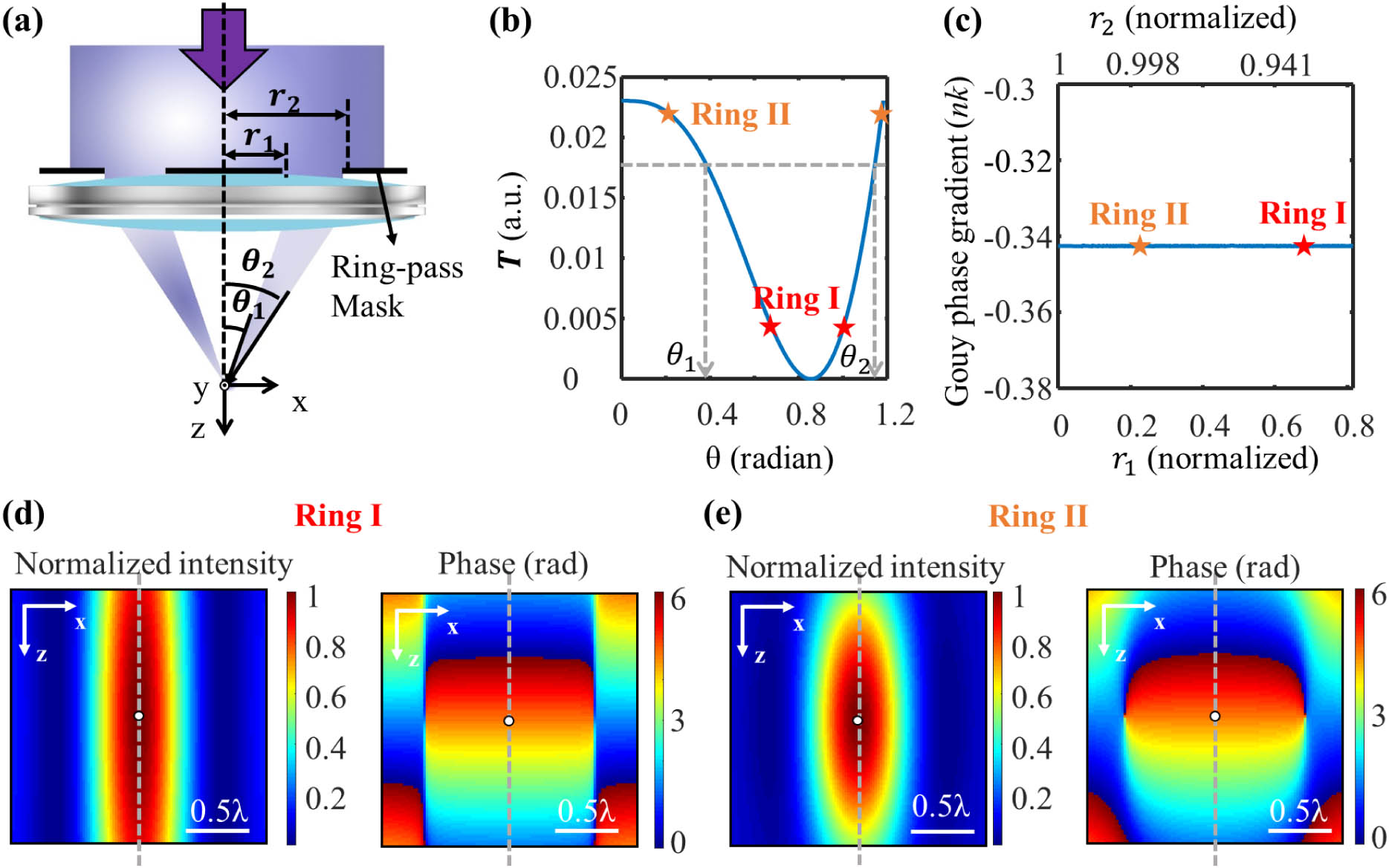
    Fig. 2. Calculation of the inner and outer radii of the inverse mask to satisfy EGPG condition. (a) Schematic of the inverse mask for a shaded-ring pupil mask; (b) radius determination tool function; (c) GPG of the inverse focus at focus center, which maintains at GPG of the clear focus, i.e., 0.3425nk; (d), (e) focus intensity and phase distribution corresponding to two pairs of inner and outer radii of the ring mask selected in (b), (c) (labeled by red and orange stars, respectively). The white dots and gray dot lines represent the focus center and the optical axis, respectively. Scale bar, half wavelength; NA of the objective,1.4; n=1.514.
    (a) Axial FWHM and sidelobe of the radially polarized beam focus with the shaded-ring pupil mask whose parameters are calculated based on EGPG; energy transmittance of the mask: 30%; (b)–(d) 2D intensity distribution in x-z cross section (b), normalized intensity profile along z axis (c), and normalized intensity profile along x axis (d) of the unmodulated and the modulated focus; sidelobe intensity, 30%; (e)–(g) total intensity distribution (e), normalized intensity profile along x and z axes (f), and intensity distribution of the longitudinal component (g) of a quasi-spherical focus.
    Fig. 3. (a) Axial FWHM and sidelobe of the radially polarized beam focus with the shaded-ring pupil mask whose parameters are calculated based on EGPG; energy transmittance of the mask: 30%; (b)–(d) 2D intensity distribution in x-z cross section (b), normalized intensity profile along z axis (c), and normalized intensity profile along x axis (d) of the unmodulated and the modulated focus; sidelobe intensity, 30%; (e)–(g) total intensity distribution (e), normalized intensity profile along x and z axes (f), and intensity distribution of the longitudinal component (g) of a quasi-spherical focus.
    Experiment on the axially superresolved focusing based on the GPG tuning. (a) Schematic diagram of converting the phase modulation to polarization direction modulation. The amplitude modulation can then be realized by adjusting the direction of polarizer after the SLM. (b) Image of the intensity distribution in the pupil plane; (c), (d) measured z profile of the focus of the (c) radially polarized beam and the (d) linearly polarized beam, respectively, with EGPG condition-based modulated pupil and unmodulated pupil. Inset in (c) is the wide-field image of an 80-nm-diameter Au nanoparticle at the focal point of the radially polarized beam.
    Fig. 4. Experiment on the axially superresolved focusing based on the GPG tuning. (a) Schematic diagram of converting the phase modulation to polarization direction modulation. The amplitude modulation can then be realized by adjusting the direction of polarizer after the SLM. (b) Image of the intensity distribution in the pupil plane; (c), (d) measured z profile of the focus of the (c) radially polarized beam and the (d) linearly polarized beam, respectively, with EGPG condition-based modulated pupil and unmodulated pupil. Inset in (c) is the wide-field image of an 80-nm-diameter Au nanoparticle at the focal point of the radially polarized beam.
    Application of the EGPG method on a π phase mask. (a) Schematic of the π phase mask; (b) axial FWHM and sidelobe of an x linearly polarized beam focus modulated by the π phase ring pupil mask; (c) axial intensity profile of the foci 1–4 labeled by circles in (b). The FWHMs are shown in the figure. The axial FWHM of focus 3 is half-shortened from the diffraction limit. (d) The 3D isosurface view of focus 3; NA of the objective, 1.4; refractive index, 1.514.
    Fig. 5. Application of the EGPG method on a π phase mask. (a) Schematic of the π phase mask; (b) axial FWHM and sidelobe of an x linearly polarized beam focus modulated by the π phase ring pupil mask; (c) axial intensity profile of the foci 1–4 labeled by circles in (b). The FWHMs are shown in the figure. The axial FWHM of focus 3 is half-shortened from the diffraction limit. (d) The 3D isosurface view of focus 3; NA of the objective, 1.4; refractive index, 1.514.
    Images in the x–z cross section of four objects with different periods (z denotes the direction of the optical axis). (a) Objects 1–4 with periods of 0.6λ,0.7λ,0.8λ, and λ, respectively; (b)–(d) images simulated considering condition 1, in which the illumination and detection are both modulated by the clear pupil, inverse pupil, and shaded-ring pupil shown in Fig. 1(a). Parameters of the shaded-ring pupil mask are the same as those demonstrated in Fig. 3(c). (e)–(g) Images simulated considering condition 2, in which only the illumination or detection is modulated; the periods of 0.6λ in (d) and 0.7λ in (g) are resolved, where the shaded-ring modulated superresolution focus is utilized. The period of 0.8λ is resolved by the original focus in (b) and (e). The axial resolution can be improved 25% in condition 1, and improved 12.5% in condition 2, while the better contrast and cleaner background are enabled in condition 2.
    Fig. 6. Images in the xz cross section of four objects with different periods (z denotes the direction of the optical axis). (a) Objects 1–4 with periods of 0.6λ,0.7λ,0.8λ, and λ, respectively; (b)–(d) images simulated considering condition 1, in which the illumination and detection are both modulated by the clear pupil, inverse pupil, and shaded-ring pupil shown in Fig. 1(a). Parameters of the shaded-ring pupil mask are the same as those demonstrated in Fig. 3(c). (e)–(g) Images simulated considering condition 2, in which only the illumination or detection is modulated; the periods of 0.6λ in (d) and 0.7λ in (g) are resolved, where the shaded-ring modulated superresolution focus is utilized. The period of 0.8λ is resolved by the original focus in (b) and (e). The axial resolution can be improved 25% in condition 1, and improved 12.5% in condition 2, while the better contrast and cleaner background are enabled in condition 2.
    Normalized intensity profile along z axis of the dual-ring-shaded pupil mask modulated focus. (a) Schematic diagram of the dual-ring-shaded pupil mask; (b) two focus profiles modulated by a single-ring-shaded pupil mask and a dual-ring-shaded pupil mask, respectively. The parameters of the single-ring mask are the same as those demonstrated in Fig. 3(c). The normalized radius of the dual-ring mask: r1, 2, 3, 4=0.469, 0.811, 0.817, and 0.974, respectively, and the amplitude attenuation factor is 0.85. The maximum sidelobe intensity is lowered in the dual-ring modulated focus. (c) Focus profiles modulated by three dual-ring-shaded pupil masks, showing that the power of sidelobes is pushed further from the central peak. Dual ring I: r1, 2, 3, 4=0.469, 0.811, 0.817, 0.974; amplitude attenuation, 0.85. Dual ring II: r1, 2, 3, 4=0.4688, 0.8107, 0.8188, 0.9736; amplitude attenuation, 0.87. Dual ring III: r1, 2, 3, 4=0.459, 0.804, 0.826, 0.975; amplitude attenuation, 0.92. All the foci possess the same power transmission efficiency (30%) and the same FWHM of the central peak (0.75λ). NA of the objective, 1.4; refractive index,1.514.
    Fig. 7. Normalized intensity profile along z axis of the dual-ring-shaded pupil mask modulated focus. (a) Schematic diagram of the dual-ring-shaded pupil mask; (b) two focus profiles modulated by a single-ring-shaded pupil mask and a dual-ring-shaded pupil mask, respectively. The parameters of the single-ring mask are the same as those demonstrated in Fig. 3(c). The normalized radius of the dual-ring mask: r1,2,3,4=0.469, 0.811, 0.817, and 0.974, respectively, and the amplitude attenuation factor is 0.85. The maximum sidelobe intensity is lowered in the dual-ring modulated focus. (c) Focus profiles modulated by three dual-ring-shaded pupil masks, showing that the power of sidelobes is pushed further from the central peak. Dual ring I: r1,2,3,4=0.469, 0.811, 0.817, 0.974; amplitude attenuation, 0.85. Dual ring II: r1,2,3,4=0.4688, 0.8107, 0.8188, 0.9736; amplitude attenuation, 0.87. Dual ring III: r1,2,3,4=0.459, 0.804, 0.826, 0.975; amplitude attenuation, 0.92. All the foci possess the same power transmission efficiency (30%) and the same FWHM of the central peak (0.75λ). NA of the objective, 1.4; refractive index,1.514.
    Schematic of experimental setup. BS, beam splitter; SLM, spatial light modulator.
    Fig. 8. Schematic of experimental setup. BS, beam splitter; SLM, spatial light modulator.
    2D focus intensity distribution in the x-z cross section of a linearly polarized femtosecond laser. (a) 2D intensity distribution of the original unmodulated focus; (b) 2D intensity distribution of the shaded-ring pupil function modulated focus based on the EGPG condition; (c) lateral intensity distribution of the two foci in (a), (b); (d) axial intensity distribution of the two foci in (a), (b); the data are fitted using the Gaussian function. The axially prolonged focus might be attributed to the interaction between the femtosecond laser with the Au nanoparticle and the optical system. Laser information: central wavelength, 800 nm; pulse width, 140 fs; Coherent Chameleon Ultra II, femtosecond laser.
    Fig. 9. 2D focus intensity distribution in the x-z cross section of a linearly polarized femtosecond laser. (a) 2D intensity distribution of the original unmodulated focus; (b) 2D intensity distribution of the shaded-ring pupil function modulated focus based on the EGPG condition; (c) lateral intensity distribution of the two foci in (a), (b); (d) axial intensity distribution of the two foci in (a), (b); the data are fitted using the Gaussian function. The axially prolonged focus might be attributed to the interaction between the femtosecond laser with the Au nanoparticle and the optical system. Laser information: central wavelength, 800 nm; pulse width, 140 fs; Coherent Chameleon Ultra II, femtosecond laser.
    (a) Transient electric field and (b) the local wave vector distribution along the z axis of foci 1–4 in Fig. 5(b); the transient electric field in (a) is the real part of the complex amplitude calculated based on the Debye theory. The local wave vector in (b) is the derivative of the phase of the electric field versus axial position. The derivative is much larger than the maximum wavenumber in the media. NA of the objective, 1.4; refractive index, 1.514.
    Fig. 10. (a) Transient electric field and (b) the local wave vector distribution along the z axis of foci 1–4 in Fig. 5(b); the transient electric field in (a) is the real part of the complex amplitude calculated based on the Debye theory. The local wave vector in (b) is the derivative of the phase of the electric field versus axial position. The derivative is much larger than the maximum wavenumber in the media. NA of the objective, 1.4; refractive index, 1.514.
    Intensity distribution in (a) x–z and (b) x–y cross section of the focus shown in Fig. 5(d).
    Fig. 11. Intensity distribution in (a) xz and (b) xy cross section of the focus shown in Fig. 5(d).
    Simulation of a deep superresolved focus of linearly polarized beam with a 0.1λ ultrasmall FWHM. (a) x–z cross-sectional view of the focus; the intensity is shown in log. (b) Axial intensity profile along the white dashed line in (a); (c), (d) distribution of the polarization ellipticity and the direction of the major axis in the x–z cross section. NA of the objective, 1.4; refractive index, 1.514.
    Fig. 12. Simulation of a deep superresolved focus of linearly polarized beam with a 0.1λ ultrasmall FWHM. (a) xz cross-sectional view of the focus; the intensity is shown in log. (b) Axial intensity profile along the white dashed line in (a); (c), (d) distribution of the polarization ellipticity and the direction of the major axis in the xz cross section. NA of the objective, 1.4; refractive index, 1.514.
    Applications of the EGPG method to design a π phase mask to modulate a radially polarized beam. (a) Axial FWHM and sidelobe of a radially polarized beam focus modulated by the π phase ring pupil mask. r1 and r2 denote the normalized radius of the ring. (b) Axial intensity profile of the foci labeled by circles in (a) of the same color. The FWHMs are shown in the figure. (c) 3D intensity isosurface distribution of the longitudinal component of the focus, in which the axial depth is shortened by half from the diffraction limit; (d) x–z cross-sectional view of the focus with a 0.096λ ultrasmall FWHM; NA of the objective, 1.4; refractive index, 1.514.
    Fig. 13. Applications of the EGPG method to design a π phase mask to modulate a radially polarized beam. (a) Axial FWHM and sidelobe of a radially polarized beam focus modulated by the π phase ring pupil mask. r1 and r2 denote the normalized radius of the ring. (b) Axial intensity profile of the foci labeled by circles in (a) of the same color. The FWHMs are shown in the figure. (c) 3D intensity isosurface distribution of the longitudinal component of the focus, in which the axial depth is shortened by half from the diffraction limit; (d) xz cross-sectional view of the focus with a 0.096λ ultrasmall FWHM; NA of the objective, 1.4; refractive index, 1.514.
    Xiaowei Liu, Xiaolan Xia, Zhuofan Yao, Tianyue Zhang, Meiling Jiang, Qing Yang, Xiangping Li, Yaoyu Cao. Theoretical and practical guide for an axial superresolved focus via Gouy phase steering[J]. Photonics Research, 2022, 10(11): 2502
    Download Citation