Abstract
We propose a depolarizer based on the principle of a collection of half-wave plates with randomly distributed optic axes. The design is demonstrated by means of dynamically photopatterning liquid crystal into randomly aligned homogeneous domains. We characterize the liquid crystal depolarizer for 1550 nm and C-band (1520–1610 nm). A degree of polarization of less than 5% is obtained for any linearly polarized light. This study provides a practical candidate for high-performance depolarizers.of China (NSFC) (Nos. 11304151, 61490714, 61435008 and 61575093).1. INTRODUCTION
Eliminating polarization of incident light beams is critical, as it may significantly affect the performance of optical apparatuses. For example, grating-based spectrometers are sensitive to the polarization of collected light [1], and the input polarization may cause errors to space-based instruments for earth observation [2]. In optical communications, especially in long-haul and high bit-rate fiber transmission systems, polarization may lead to impairments such as polarization mode dispersion, polarization dependent loss/gain, and polarization hole burning [3,4]. To address these issues, depolarizing has to be introduced.
To date, two main strategies have been proposed. Polarization scrambling is a temporal depolarization approach that rapidly varies the state of polarization (SOP) of incident light to randomize the average polarization over time. Typical polarization scramblers include lithium niobate waveguides [5,6], reentrant Lefèvre controllers [7], fiber squeezers [8], etc. These methods suffer from bulkiness, high cost, power consumption, or restrictions of input polarization. A depolarizer is another depolarization approach, which decreases the degree of polarization (DOP) in space or wavelength domain. The commonly available devices are wedge [9], the Loyt type [10,11], and microretarder array [12] depolarizers, respectively. However, these devices are polarization dependent or mainly effective for broadband light. Depolarizers based on a liquid crystal (LC) particle dispersion system [13], randomly orientated LC polymer [12] or LC [1] domains and can avoid the above drawbacks with simplified configurations. Unfortunately, the strong scattering induces optical loss for the former two, while the last one requires a complicated and time-consuming manufacture process. Therefore, efforts toward high-efficiency, polarization independent, and easily fabricated depolarizers are of great significance.
In this work, we propose a novel LC depolarizer with randomly aligned homogeneous domains. The design is demonstrated by means of dynamic photopatterning technique [14], which is suitable for the creation of high-quality LC alignment in high resolution [15,16]. The LC depolarizer is applicable for a wide wavelength range and monochromatic light in the telecom band. The obtained DOP is less than 5% without the limitation of input polarization. The overall performances of the depolarizer reach the requirements for practical use.
Sign up for Photonics Research TOC. Get the latest issue of Photonics Research delivered right to you!Sign up now
2. PRINCIPLES AND EXPERIMENTS
Wave plates are commonly used to alter the SOP of incident light, among which half-wave plates can rotate the polarization vector by an angle ( is the angle between the input polarization direction and the optic axis of the waveplate). The proposed depolarizer is a collection of half-wave plates with optic axes randomly distributed. After passing through such a depolarizer, the linearly polarized light is converted to a mixture of various polarized components; thus, the DOP drastically decreases. The concept is schematically illustrated in Fig. 1. The depolarizer is composed of square areas, each acting as a uniform half-wave plate. Eighteen gray scales from white to black indicate the optic axes being 0 to ians with an interval of .
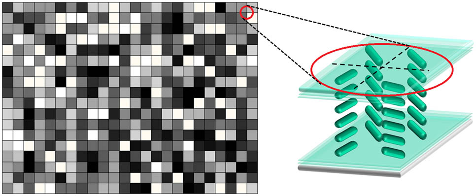
Figure 1.Illustration of the LC depolarizer. Different directions of optic axes are indicated by different gray scales. The inset depicts the LC orientations in the red circle.
LCs can be utilized to realize the above design due to their announced birefringence. A digital micro-mirror device (DMD) based [17] on a dynamic photopatterning technique is adopted. The sulphonic azo-dye SD1 is used as the photoalignment agent, which tends to reorient perpendicularly to the UV polarization with a dose of [18]. The orientation of SD1 will further guide that of LC molecules. Two pieces of glass substrates () were spin-coated with SD1 and sealed with epoxy glue with 4 μm spacers to form the cell. Then, it was placed at the image plane of the exposure system to record the polarization patterns [19,20]. The whole exposure area is divided into squares, and 18 patterns composed of 24 squares, respectively, are randomly selected through MATLAB, as exhibited by the images in green rectangles in Fig. 2. It is noteworthy that there is no overlap among exposure patterns, so that every square is exposed only once. Each pattern is endowed with one UV polarization direction, from 0 to in an interval of . The images in red rectangles in Fig. 2 correspondingly present the accumulated polarization information. After a 15 min step-by-step exposure process, a pseudo-randomly aligned orientation of SD1 is constructed. Finally, when LC E7 is capillarily filled, the directors randomly distributed LC depolarizer is formed (Fig. 1 inset).

Figure 2.Flow sheet of the exposure process. Images in green rectangles are exposure patterns for each step; images in red rectangles present the accumulated polarization information correspondingly.
3. RESULTS AND DISCUSSIONS
Figure 3 shows a micrograph of the LC depolarizer under crossed polarizers. The reddish color is attributed to the corresponding wavelength, which satisfies the half-wave condition here. The bright regions indicate that the LC directors are about 45° or 135° with respect to the polarizer of the microscope, whereas the dark regions indicate 0° or 90° [21,22]. Accordingly, the gray scales between bright and dark are halved compared with those of the original design. When rotating the sample under the microscope, the dark and bright regions interconvert, confirming the varying of the LC directors. Here, the cell gap is much smaller than the size of each square area. Additionally, thanks to the high anchoring energy of SD1, the alignment of LC can be precisely controlled, which has been directly proved in our previous work via 2D Stokes parameters measurement [19]. The dispersed dark points are spacers, and the existence of boundary lines results from the disclination between adjacent orientations with distinguished difference [23].
Figure 3.Micrograph of the LC depolarizer, with the arrows indicating the directions of the analyzer and polarizer. Scale bar is 100 μm.
DOP is a quantity commonly applied to describe the performance of a depolarizer. According to the definition of DOP: where , , , and are Stokes parameters. The DOP represents the polarization degree of a light beam: the DOP of perfectly polarized light is 100%, whereas the DOP of unpolarized light is 0%. The DOP between 0% and 100% corresponds to the partially polarized wave. Smaller DOP values mean better depolarizing effects. For a linearly polarized light passing through the LC depolarizer, the Stokes parameters calculated by Mueller matrix are expressed as [1] where is the angle between the optic axis of the half-wave plates and the axis, and is the angle between the incident polarization direction and the axis. Herein, the axis is defined as the longer side of the depolarizer. For a fixed : where is the width of the LC depolarizer, is that of th half-wave plate, and is the number of the half-wave plates. Theoretically, more columns (i.e., smaller ) and smaller intervals (i.e., more values) will lead to smaller and , thus the depolarizing effects should be better. But too small intervals and would result in a time-consuming diffraction loss. Moreover, the denser disclination lines would cause extra scattering loss. Herein, is about 58 μm, is 1/24 for the direction, 1/18 for direction, and varies from 0 to and is 432. The calculation results of Eqs. (3) and (4) approximate zero. In our experiment, a polarimeter (Thorlabs, PAX5710IR3-T) is employed to measure the DOP of the transmitted light, and a polarizer is used to control the incident polarization. An amplified spontaneous emission (ASE) source (1520–1610 nm) and a 1550 nm laser with beam size in diameter are adopted to verify the depolarizing effect for a wide wavelength range and monochromatic light in the telecom band.
Figure 4 shows the DOP results at different incident polarization. Blue dots and error bars represent the average DOP values and the corresponding for ASE source (1520–1610 nm); red dots and error bars are those of the 1550 nm laser. From the chart, we can see that all the DOP is less than 5%, indicating that the depolarizer is effective for broadband and monochromatic light without the limitation of input polarization. Furthermore, the minimum DOP obtained is only 0.156% and 0.384% for the ASE source and 1550 nm laser, respectively. The overall performances of the proposed depolarizer are superior to those of previously reported approaches. The transmittance of our LC depolarizer @ 1550 nm is 62.1% with the loss mainly caused by the high reflectivity of ITO glass at the telecom band. To further improve the transmittance, high-transparent electrodes, such as single layer graphene, and antireflectance coating techniques, can be introduced.
Figure 4.DOP results at different incident polarization. Blue dots stand for the DOP for ASE source; red dots stand for those of the 1550 nm laser.
In our work, 4 μm spacers were chosen to satisfy the half-wave condition for the tested wavelength with no need for voltage driving. The condition is valid for the infrared range where the birefringence of LC E7 is not changing much. Moreover, the cell gap can be optimized for a narrow wavelength range or monochromatic light in the other band (visible, infrared, or terahertz [24,25]). It is worth mentioning that the SD1 could be reoriented by blue or UV light, which restricts its applications in the corresponding wavelength range. However, the problem could be solved by introducing non-erasable alignment agents [26]. Additionally, thanks to the electro-optical tunability of LCs, the depolarizer could also be electrically tuned to operate at different wavelengths, and the switch between ON and OFF states of the depolarization is achievable. Previous researches mostly focus on the depolarization of linearly polarized light. Here, we further studied the depolarizing effects in the whole process from linear to circular polarization. We found that the DOP would increase gradually from to nearly 100%. Fortunately, by electrically tuning the phase retardation to quarter-wave condition, the DOP of incident circular polarization was suppressed to as well. For intermediate cases, the DOP could also be effectively reduced via optimizing the phase retardation. The size of our LC depolarizer is , which perfectly matches the diameter of the beam used in the characterization setup (). Because the minification and magnification can be easily tuned by adjusting the objective in the DMD microlithography system, the size of final LC depolarizer is adjustable to satisfy incident beams with different sizes, thus enabling the LC depolarizer obtain high depolarization performances under different situations.
4. CONCLUSION
We demonstrated a novel LC depolarizer with randomly aligned homogeneous domains via dynamic photopatterning technique. For any linearly polarized light in the telecom band, the obtained DOP is reduced to . Excellent depolarization effects could also be achieved for other incident polarization with optimized phase retardation. The LC depolarizer possesses additional merits, such as easy fabrication, low cost, and compact configuration, making it promising in the fields of optical instruments and optical communications.
ACKNOWLEDGMENT
Acknowledgment. The authors are indebted to Prof. V. Chigrinov for his kind support with the photoalignment technique. This work was sponsored by the National Natural Science Foundation of China (NSFC) (Nos. 11304151, 61490714, 61435008 and 61575093).
References
[1] M. Honma, T. Nose. Liquid-crystal depolarizer consisting of randomly aligned hybrid orientation domains. Appl. Opt., 43, 4667-4671(2004).
[2] P. Schau, L. Fu, K. Frenner, M. Schäferling, H. Schweizer, H. Giessen, L. M. G. Venancio, W. Osten. Polarization scramblers with plasmonic meander-type metamaterials. Opt. Express, 20, 22700-22711(2012).
[3] V. Mazurczyk, J. Zyskind. Polarization dependent gain in erbium doped-fiber amplifiers. IEEE Photon. Technol. Lett., 6, 616-618(1994).
[4] K. Perlicki. Investigation of the state of polarization distribution generated by polarization scramblers on the Poincaré sphere. Opt. Commun., 252, 58-63(2005).
[5] F. Heismann, D. Gray, B. Lee, R. Smith. Electrooptic polarization scramblers for optically amplified long-haul transmission systems. IEEE Photon. Technol. Lett., 6, 1156-1158(1994).
[6] F. Heismann, R. W. Smith. High-speed polarization scrambler with adjustable phase chirp. IEEE J. Sel. Top. Quantum Electron., 2, 311-318(1996).
[7] Y. K. Lizé, R. Gomma, R. Kashyap, L. Palmer, A. Willner. Fast all-fiber polarization scrambling using re-entrant Lefevre controller. Opt. Commun., 279, 50-52(2007).
[8] L. Yao, H. Huang, J. Chen, E. Tan, A. Willner. A novel scheme for achieving quasi-uniform rate polarization scrambling at 752 krad/s. Opt. Express, 20, 1691-1699(2012).
[9] S. C. McClain, R. A. Chipman, L. W. Hillman. Aberrations of a horizontal-vertical depolarizer. Appl. Opt., 31, 2326-2331(1992).
[10] J. C. G. de Sande, G. Piquero, C. Teijeiro. Polarization changes at Lyot depolarizer output for different types of input beams. J. Opt. Soc. Am. A, 29, 278-284(2012).
[11] A. Shaham, H. S. Eisenberg. Realizing a variable isotropic depolarizer. Opt. Lett., 37, 2643-2645(2012).
[12] . Microretarder Depolarizer Array.
[13] N. J. Diorio, M. R. Fisch, J. L. West. Filled liquid crystal depolarizers. J. Appl. Phys., 90, 3675-3678(2001).
[14] B. Y. Wei, P. Chen, W. Hu, W. Ji, L. Y. Zheng, S. J. Ge, Y. Ming, V. Chigrinov, Y. Q. Lu. Polarization-controllable Airy beams generated via a photoaligned director-variant liquid crystal mask. Sci. Rep., 5, 17484(2015).
[15] M. Schadt, K. Schmitt, V. Kozinkov, V. Chigrinov. Surface-induced parallel alignment of liquid crystals by linearly polymerized photopolymers. Jpn. J. Appl. Phys., 31, 2155-2164(1992).
[16] M. Schadt, H. Seiberle, A. Schuster. Optical patterning of multi-domain liquid-crystal. Nature, 381, 212-215(1996).
[17] H. Wu, W. Hu, H. C. Hu, X. W. Lin, G. Zhu, J. W. Choi, V. Chigrinov, Y. Q. Lu. Arbitrary photo-patterning in liquid crystal alignments using DMD based lithography system. Opt. Express, 20, 16684-16689(2012).
[18] V. Chigrinov, S. Pikin, A. Verevochnikov, V. Kozenkov, M. Khazimullin, J. Ho, D. D. Huang, H. S. Kwok. Diffusion model of photoaligning in azo-dye layers. Phys. Rev. E, 69, 061713(2004).
[19] B. Y. Wei, W. Hu, Y. Ming, F. Xu, S. Rubin, J. G. Wang, V. Chigrinov, Y. Q. Lu. Generating switchable and reconfigurable optical vortices via photopatterning of liquid crystals. Adv. Mater., 26, 1590-1595(2014).
[20] P. Chen, W. Ji, B. Y. Wei, W. Hu, V. Chigrinov, Y. Q. Lu. Generation of arbitrary vector beams with liquid crystal polarization converters and vector-photoaligned q-plates. Appl. Phys. Lett., 107, 241102(2015).
[21] I. C. Khoo, S. T. Wu. Optics and Nonlinear Optics of Liquid Crystals(1993).
[22] P. Chen, B. Y. Wei, W. Ji, S. J. Ge, W. Hu, F. Xu, V. Chigrinov, Y. Q. Lu. Arbitrary and reconfigurable optical vortex generation: a high-efficiency technique using director-varying liquid crystal fork gratings. Photon. Res., 3, 133-139(2015).
[23] X. W. Lin, W. Hu, X. K. Hu, X. Liang, Y. Chen, H. Q. Cui, G. Zhu, J. N. Li, V. Chigrinov, Y. Q. Lu. Fast response dual-frequency liquid crystal switch with photo-patterned alignments. Opt. Lett., 37, 3627-3629(2012).
[24] S. T. Wu. Birefringence dispersions of liquid crystals. Phys. Rev. A, 33, 1270-1274(1986).
[25] L. Wang, X. W. Lin, W. Hu, G. H. Shao, P. Chen, L. J. Liang, B. B. Jin, P. H. Wu, H. Qian, Y. N. Lu, X. Liang, Z. G. Zheng, Y. Q. Lu. Broadband tunable liquid crystal terahertz wave plates driven with porous graphene electrodes. Light: Sci. Appl., 4, e253(2015).
[26] M. Schadt, H. Seiberle. Optical patterning of multidomain LCDs. J. Soc. Inf. Display, 5, 367-370(1997).

