1State Key Laboratory of Applied Optics, Changchun Institute of Optics, Fine Mechanics and Physics, Chinese Academy of Sciences, Changchun 130033, China
2University of Chinese Academy of Sciences, Beijing 100049, China
Lina Shao, Zhaoliang Cao, Quanquan Mu, Lifa Hu, Yukun Wang, Shaoxin Wang, Li Xuan, "Design of a dynamic refocus system based on the Seidel aberration theory," Chin. Opt. Lett. 14, 042202 (2016)
Copy Citation Text
This Letter presents an optical design method based on the Seidel aberration theory for dynamic refocus systems. The function of a dynamic refocus system is to increase the amount of return photons when a pulsed laser travels over an extended height range. In this study, the dynamic refocus system is a short focal image system. The aberrations of the dynamic refocus system are calculated individually. Aplanatic lenses are used to eliminate the main spherical aberration. A field lens is used to change the stop position in order to eliminate comas and astigmatism. The effectiveness of the initial design results are confirmed, and the designed dynamic refocus objective with an aperture of F-number 0.98 and a focal length of 14.325 mm is achieved. The total motion of the dynamic refocus mirror is approximately 216 μm at heights that ranged from 8 to 18 km. The optimum result shows that the dynamic refocus system is an ideal optical image system at each conjugating height with 10 km sample thicknesses.
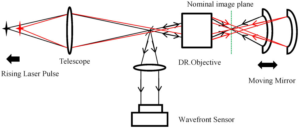
Adaptive optics systems have been used to correct the atmospheric distortion in astronomical observations[1–3]. Laser guide stars (LGSs) enhance sky coverage, and therefore they have become a promising candidate for large telescope adaptive optics systems[4–6]. However, the problem of spot elongation prevents them from being practically applied[7]. Spot elongation is generated when the sample range of LGS height is larger than the seeing-limited depth of field. Generally, the sample range is restricted to the range of 1–2 km, and thus most of the backscattered photons of LGS are lost[8]. A dynamic refocus (DR) system has been put forward by Georges et al. to overcome this problem[9–12]. As shown in Fig. 1, the operating mechanism of the DR system is a dynamically driven mirror in a wavefront optical sensor train that maintains focus on a fixed plane while the laser pulse goes through the atmosphere over an extended height range.
Unfortunately, the velocity of the focal plane is in the order of km/s, which is incompatible with mechanically driven mirrors. Therefore, a short-focus objective is needed for the DR system to greatly reduce changes in the sagittal depth and thus reduce the velocity of the mirror. Because a short-focus objective operates at a very fast F-number within a field angle, it is important that the starting point of the design provides reasonable aberration correction. The initial design can be optimized for performance. In this Letter, a novel method based on the Seidel aberration theory is introduced, making it possible to design a DR optical system.
Before the design, the effective focal length (EFL) of the DR objective should be obtained. The EFL of the DR objective is dependent on its longitudinal magnification. The longitudinal magnification is expressed by the ratio of the image longitudinal motion to that of object, , which is given by[9]where represents the sample thickness of LGS, represents the focal plane displacement, represents the height of LGS, represents the image distance of LGS, and represents the EFL of the system.
Sign up for Chinese Optics Letters TOC. Get the latest issue of Chinese Optics Letters delivered right to you!Sign up now
This study considered a 1.23 m telescope (CIOMP, China), for which is 56 mm (, , ). The time that light takes to travel from 8 to 18 km in double passes is 66.67 μs, which gives the moving focal plane a speed of approximately 840 m/s. This is obviously not a realizable speed for moving the mirror. If the velocity of the mirror is reduced to 3 m/s, its displacement will be approximately 200 μm. Because the mirror acts as a 4f imaging system, the displacement of the image plane is two times the mirror movement, resulting in a of 400 μm. Hence, the EFL of the system is reduced to 2.3 m, according to Eq. (1). If the distance from the focus of the telescope to the DR objective is 300 mm, then the distance between the telescope and the DR objective, termed as , is 25.3 m. The EFL of a system consisting of two separate components is given by[13]where , , and ; consequently, the EFL of the DR objective . This short focal objective will introduce a large amount of spherical aberrations.
The second parameter of the DR system is the field of view (FOV). The LGS should be in the isoplanatic angle range where the wavefront error between the LGS path and the observation target differs by 1 rad[14]. The FOV of the telescope is approximately 15 arcsec. Astigmatism, comas, and a Petzval curvature are of more concern resulting from the field.
Chromatic effects are ignored in this design because the Rayleigh LGS is operated at a single wavelength of 532 nm.
First, the Seidel aberration theory is used to analyze and eliminate the spherical aberrations. The Seidel sum polynomial term of spherical aberrations is expressed as[15]There are three cases where a simple spherical surface is aplanatic[13]. One occurs when the object and image are both located on the surface (). The second case is when both the object and image are at the center of curvature of the surface (). Finally, the third case () occurs when the object and image distances are related by where is the radius of the surface. The function of the aplanatic lenses is to provide a large numerical aperture without bringing spherical aberrations. Therefore, aplanatic lenses are chosen as the top candidate for the original structure of the DR objective.
As seen in Fig. 2, lens 1 and lens 2 are a combination of aplanatic lenses, where surface satisfies the first aplanatic case, surfaces and satisfy the third case, and surface satisfies the second case. There is no axial gap between these two elements. Lens 3 is in front of the combination of aplanatic lenses to make the rays from the telescope converge and meet the aplanatic conditions.
The following assumptions are made: the thicknesses of lens 1 and lens 2 are the same, , lens 2 is an equiconvex singlet, , and the lenses are made of the same material. Consequently, the radii of the surfaces are expressed as
Then the EFLs of lens 1 and lens 2 can be obtained from the radii of the surfaces. In Fig. 2, the blue lines represent the principal planes of lens 1 and lens 2. The positions of the principal planes are dependent on the shape of the lenses. In this situation, the positions of the principal planes are calculated by the following:
The positive sign represents the direction of ray propagation. The distance between lens 1 and lens 2 is
The positions of the principal planes for aplanatic lenses are calculated by the following: where is the EFL of lens 1, is the EFL of lens 2, and is the combined EFL of lens 1 and lens 2. Assume that lens 3 is an ideal thin lens in front of lens 2, and the principal planes are themselves. Then the distance between lens 3 and the combination of aplanatic lenses is
The EFLs of lens 1 and lens 2 ( and ) can be obtained from the radii of the surfaces by using Eq. (5). Then the combined EFL of lens 1 and lens 2 () is calculated from given by Eq. (7). Finally, the EFL of the front lens 3 () is obtained from the objective and image distances relations of L3 and L′3. As seen from Eqs. (5)–(9), all the parameters can be obtained when the index, thicknesses of the aplanatic lenses (), and the EFL of the DR objective () are given. ZF2 glass with a refractive index of 1.67 was chosen because its high index would help minimize the lens curvatures. Thus, the relationship between and is established by a discrete numerical calculation. The EFL of the DR objective varies with the thickness of the aplanatic lenses as shown in Fig. 3, where the dots represent the calculated data and the line is the fitted curve. The line is fitted by a linear function as
Figure 3.Thickness of aplanatic lenses as a function of the EFL of the DR objective.
In this Letter, ; therefore, is approximately 14 mm. According to Eqs. (5)–(9), the parameters of the original structure for the DR objective are obtained.
The original structure for the DR objective using the combination of aplanatic lenses is well corrected for the on-axis aberrations. However, it suffers from strong off-axis aberrations, coma, astigmatism, and Petzval curvature. A very simple yet powerful approach to correcting off-axis aberrations without affecting spherical aberrations is to make the aperture stop at the proper position with respect to the lens.
Because the coma and astigmatism are correlated with the stop position, they are discussed together here. The Seidel sum polynomial terms for coma and astigmatism are given by[15]
We use the PW method to express the Seidel sum polynomial terms to reduce the parameters. Here, the and parameters are the aberration characteristic parameters of the optics system[15]. They are defined as:
Then Eq. (12) is expressed as where represents the height of light at the stop, represents the aperture of the light beam, is the power of the lens, and is the Lagrange invariant of the optics system, . Figure 4 shows the changes in aberrations from the under-correction to over-correction of the coma and astigmatism by stop shifting. The coma decreases linearly as the stop moves toward the object. The astigmatism is a quadratic function of the stop position and is plotted as a parabola. Note that astigmatism has a minimum absolute value at the stop position for which the coma is zero.
Figure 4.Effect of stop position on coma and astigmatism.
A field lens is applied for correcting or balancing coma and astigmatism aberrations. The field lens conjugates to the height of the LGS and reimages the entrance pupil near the DR system. The minimum sum of the coma and astigmatism aberrations exists for a special EFL of the field lens.
Finally, the Petzval field curvature is analyzed based on the Seidel aberration theory. The Seidel sum polynomial term of the Petzval field curvature is given by
In the DR system, Eq. (14) is rewritten as where represents the power of the DR objective and represents the power of the DR mirror.
Because the Lagrange invariant is a constant, the magnitude of the Petzval field curvature is dependent solely on the surface powers and refractive index . In order to obtain a flat field, this sum must be minimized. As the power of the DR objective is given and has a positive value, the power of the DR mirror is coincidentally negative. Therefore, the sum is zero when is equal to (). Namely, the EFL of the DR mirror is equal to (). Consequently, is equal to 21.71 mm when and .
The mirror matches the F-number of the DR objective. The center of its curvature is on the image plane of the DR objective. In this situation, the incident and emergent rays coincide and , resulting in being equal to zero, according to Eq. (3), and being equal to zero, according to Eqs. (12) and (13). Therefore, the DR mirror does not bring additional spherical aberrations or comas when its center is on the image plane of the DR objective.
It is essential that the DR mirror is near the pupil position so that the movements of 200 μm do not cause a noticeable displacement of the image. If the DR mirror is at the pupil (), then is equal to , according to Eq. (13). Because the power of the DR mirror is negative (), the DR mirror brings negative astigmatism, which can be used to balance the positive astigmatism brought by the DR objective.
The EFL of the DR mirror is dependent on the EFL of the field lens. The relations between them are shown in Fig. 5. The EFL of the field lens is approximately 283 mm when the EFL of the DR mirror approximates to .
Figure 5.EFL relations between field lens and DR mirror.
According to the above aberration analysis, the initial structure that satisfied the objective is shown in Fig. 6. The EFL of the field lens is 283 mm (not shown in Fig. 6). The image of the telescope pupil by the field lens is at 15.16 mm in front of the DR objective, and the exit pupil of the system is at 40.69 mm behind the DR objective. The DR mirror is at the exit pupil. The Seidel aberration coefficients diagram of the initial structure is shown in Fig. 7, which shows the aberration status of each surface for the DR system in the light importing and exporting situations. The red rectangles represent spherical aberrations, the green represents coma aberrations, the violet represents astigmatism, and the blue represents the field curvature. The grid lines are spaced at 0.5 μm, approximating to (μ). The DR objective always generates the positive astigmatism, which can be balanced by the negative astigmatism of the DR mirror. The main aberration is field curvature with a coefficient value of ; other aberrations are neglected, as the coefficient values are less than .
The field lens and lens 3 are replaced by paraxial surfaces for convenience in the initial structure. The radii of the surfaces are calculated from their EFL values. All the radii and the thicknesses of the DR system are set as variables, and optimized using Zemax software. The final designed DR objective has an aperture of F/0.98 and a focal length of 14.325 mm.
As the depth of field is approximately 1 km, the conjugating height is sequentially raised, starting from 8 km and increasing in 1 km increments to a maximum of 18 km. Figure 8 shows the spot diagram of the DR system at each conjugating height. The image spots are in the Airy diameter range, which suggests that the DR system is an ideal optical system. Table 1 summarizes the final data of the DR system at the conjugating height of 11 km. Figure 9 shows the optimized results of the movement distance for the DR mirror. The 10 km sample thicknesses generate approximately 43.2 mm longitudinal displacement on the telescope image plane, and pass through the DR objective; the movement distance for the DR mirror is approximately 216 μm, and its velocity is reduced to 3.2 m/s.
Figure 8.Spot diagram at different conjugate heights.
In conclusion, we present an optical design method based on the Seidel aberration theory for a DR system. First, an aplanatic lens combination is chosen as the top candidate to eliminate the main spherical aberration. The relation between the thickness of the aplanatic lenses and the EFL of the DR objective is deduced, and is a linear function. Using this function, the initial parameters of the DR objective are obtained. Then, comas and astigmatism are eliminated on the basis of the effect of the stop position. The stop position of the DR system is controlled by the field lens. Then, the Petzval field curvature is eliminated by choosing the proper EFL of the DR mirror according to the Seidel sum of the Petzval field curvature. Finally, the DR system is designed by Zemax software according to the parameters calculated before. The optimum result shows that the DR system is an ideal imaging system at each conjugating height in 10 km sample thicknesses. The corresponding motion of the mirror is approximately 216 μm in the height range of 10 km, and its velocity is reduced to 3.2 m/s. The result shows the validity of the method as an initial design tool for a DR optical system. This method can be applied to arbitrary DR systems for different telescope systems.
Lina Shao, Zhaoliang Cao, Quanquan Mu, Lifa Hu, Yukun Wang, Shaoxin Wang, Li Xuan, "Design of a dynamic refocus system based on the Seidel aberration theory," Chin. Opt. Lett. 14, 042202 (2016)