
Tao Zhong, Hou Zhang. Spoof surface plasmon polaritons excited leaky-wave antenna with continuous scanning range from endfire to forward[J]. Chinese Physics B, 2020, 29(9):
- Chinese Physics B
- Vol. 29, Issue 9, (2020)
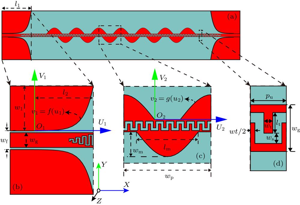
Fig. 1. Configurations of the proposed LWA based on SSPPs excitation transmission line. (a) Top view of proposed LWA. (b) Details of the feeding and transiting part. (c) Details of the radiating part. (d) Unit cell of transmission line.
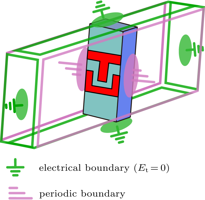
Fig. 2. The electromagnetic model of the transmission line unit cell in simulated condition.
Fig. 3. Dispersion diagram of SSPPs transmission line unit cell with varying structural parameters.
Fig. 4. Surface current distributions of the two fundamental modes: (a) 1st mode, (b) 2nd mode.
Fig. 5. Photograph of the fabricated sample.
Fig. 6. The simulated and measured S -parameters of the proposed LWA.
Fig. 7. The simulated and measured normalized radiation patterns of the proposed LWA: (a) 4 GHz, (b) 5 GHz, (c) 6 GHz, (d) 7 GHz, (e) 8 GHz, (f) 9 GHz, (g) 10 GHz.
Fig. 8. The simulated and measured beam direction angle and realized gain of the proposed LWA.
|
Table 1. Parameters values for the unit cell in unit mm.
|
Table 2. Performances comparing between the LWA and previous works.


Set citation alerts for the article
Please enter your email address

© Copyright 2018-2021 | Chinese Laser Press. All Rights Reserved 沪ICP备15018463号-20