Abstract
We report an index-coupled distributed feedback quantum cascade laser by employing an equivalent phase shift (EPS) of quarter-wave integrated with a distributed Bragg reflector (DBR) at . The EPS is fabricated through extending one sampling period by 50% in the center of a sampled Bragg grating. The key EPS and DBR pattern are fabricated by conventional holographic exposure combined with the optical photolithography technology, which leads to improved flexibility, repeatability, and cost-effectiveness. Stable single-mode emission can be obtained by changing the injection current or heat sink temperature even under the condition of large driving pulse width.1. INTRODUCTION
The quantum cascade laser (QCL) was demonstrated first in 1994 [1]. As special semiconductor lasers, QCLs are light sources covering from the mid-/far-infrared to the terahertz wavelength range. Therefore, QCLs can meet the increasing needs of applications in gas sensing, high-resolution spectroscopy, and industrial process monitoring. For practical reasons, stable single-mode emission is required. To achieve this aim, QCLs can be fabricated as distributed feedback (DFB) or distributed Bragg reflector (DBR) lasers. DFB QCLs have attracted much attention for compactness, simple fabrication, and low cost. Remarkable progress in improving device performance has been made [2–5]. In particular, the leading buried grating approach with an index-coupled mechanism is advantageous for small waveguide loss, and it can achieve very low threshold current density. However, the precise control of lasing wavelength and its stability is still a challenge for conventional index-coupled DFB QCLs. This is because those periodic structures are dispersive, and they have stopbands of frequencies in which propagation is forbidden. For the index-coupling mechanism, the stopband is at the center of the Bragg wavelength, and the spectrum is symmetric with respect to the Bragg wavelength [6–8]. Specifically, the two DFB band-edge modes with lower optical loss will lase. However, the optical loss is influenced by the facet random phase, which is difficult to precisely control. As a result, true single-mode operation maybe prevented when the two band-edge modes experience approximately the same amount of gain and loss, and mode hopping often occurs [9,10]. For solving this problem, an efficient method is employing a quarter-wave () phase shift (PS) in the grating region [11]. However, a PS grating cannot be fabricated by conventional holographic exposure and is usually manufactured by electron-beam lithography (EBL), which is high cost and time consuming. Complex-coupled surface grating DFB QCLs can lift the degeneracy of the two gap modes. However, the metal in grating grooves induces optical loss and thus increases threshold current density, which will bring back the thermal issue on performance [12,13]. Since the stable single-mode operation of DFB QCLs is significant for practical applications, any effective solution should be extensively accumulated and studied.
In this work, we designed and fabricated an index-coupled DFB QCL by employing an equivalent phase shift (EPS) of a integrated with a DBR at . Stable single-mode emission can be obtained by changing the injection current or heat sink temperature even under the condition of large driving pulse width.
2. DEVICE DESIGN AND FABRICATION
An EPS of the integrated with the DBR was fabricated based on conventional holographic exposure combined with optical photolithography technology. The designed device structure is shown in Fig. 1. The designed periods of the first-order uniform seed grating and sampled grating are and , respectively. The EPS of the is constructed only in the DFB section, where the luminous zone is. The lengths of the DFB and DBR sections are 1.35 and 1.85 mm, respectively. The DFB and DBR sections are separated by a 300 μm wide groove.
Sign up for Photonics Research TOC. Get the latest issue of Photonics Research delivered right to you!Sign up now
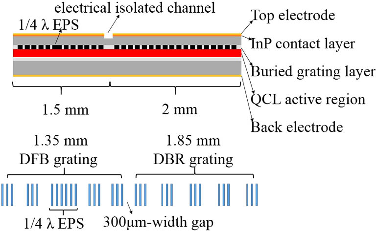
Figure 1.Device structure of the DFB QCL integrated with a DBR.
Figure 2 is the simulated transmission and reflection spectra of the different DFB QCL grating structures based on the transfer matrix method (TMM) by MATLAB. Figure 2(a) is the transmission spectrum of the conventional uniform grating. The inset displays the detail of the transmission spectrum near the Bragg wavelength, where there are two band-edge modes. Figure 2(b) is the transmission spectrum of the uniform sampled grating. Every high-order mode also has two band-edge modes similar to the inset of Fig. 2(a). Figure 2(c) is the transmission spectrum of the uniform sampled grating with the EPS of the . After employing the EPS of the , the odd-order modes can generate a PS, which breaks down the stopbands of frequencies of the odd-order modes and brings in defect modes in the center of the stopbands. As a result, the defect mode becomes the lasing mode. The inset clearly shows the defect mode of the positive first-order mode. The other odd modes have similar results to the positive first-order mode. The only difference is that the threshold increases with the wavelength spacing from the Bragg wavelength. That is to say, the higher order modes require higher thresholds.

Figure 2.(a) Transmission spectrum of the uniform grating. The inset shows the detail near the Bragg wavelength. (b) The transmission spectrum of the uniform sampled grating. (c) The transmission spectrum of the uniform sampled grating with the EPS of the . The inset displays the detail of the positive first-order mode. (d) The blue line is the transmission spectrum of the uniform sampled grating with the EPS of the , and the red line is the reflection spectrum of the DBR section of the DFB QCL integrated with a DBR.
In our experiment, we select the defect mode of the positive first-order mode as the lasing mode. Figure 2(d) is the schematic diagram of our lasers working. As we have seen, the red line is the reflection spectrum of the sampled grating DBR and the blue line is the transmission spectrum of the DFB section with the EPS of the . The stopband of the active DFB section with the EPS of the is broken down by the EPS of the . The defect mode becomes the lasing mode. Here we call the defect mode the main mode. Then the stopband of the passive sampled grating DBR just covers the main mode, which means that the main mode cannot be propagated in the passive sampled grating DBR. Therefore, the main mode has higher reflectivity and can attain more feedback. On the other hand, the two band modes locate outside the stopband of the passive sampled grating DBR, so the two side modes have lower reflectivity. As a result, stable single-mode emission can be attained. The longer length of the sampled grating DBR can ensure that the main mode locates inside its stopband and the side modes locate outside its stopband.
The QCL structure was grown on an n-InP substrate by solid-source molecular beam epitaxy. A 1.55 μm active core was sandwiched between two 300 nm thick InGaAs confinement layers. The grating was defined on the upper InGaAs confining layer using holographic lithography combined with conventional photolithography. The manufacturing details of the grating are as follows. First, manufacture a uniform grating pattern using a holographic exposure system, then make the sampled grating in the foundation of the uniform grating pattern. Finally, etch the grating by wet chemical etching to a depth about 130 nm. Then the top waveguide consisting of a 3 μm thick upper InP cladding layer, a 0.2 μm gradually doped InP layer, and a 0.5 μm thick highly doped InP contact layer was grown by metal organic vapor phase epitaxy.
After the implementation of re-growth, the wafer was processed into a double-channel ridge waveguide laser with an average core width of 9 μm. A 450 nm thick layer was then deposited by plasma enhanced chemical vapor deposition for insulation around the ridges, and electrical contact was provided by a Ti/Au layer deposited by electron beam evaporation. An additional 5 μm thick gold layer was electroplated to further improve heat dissipation. Then a 300 μm width 1 μm depth electrical isolation gap was fabricated by dry etching for implementing electrical isolation between the DFB and DBR sections. After being thinned down to about 140 μm, a Ge/Au/Ni/Au metal contact layer was deposited on the substrate side of the wafer. The waveguides were finally cleaved into 3.5 mm long bars. The lasers were mounted epilayer side up on an AlN heat sink with indium solder for effective heat dissipation.
3. RESULTS AND DISCUSSION
The spectra of devices were tested by a Fourier transform infrared spectrometer with a resolution of in rapid scan mode. The lasers were then wire bonded and mounted on a holder containing a thermistor combined with a thermoelectric cooler to monitor and adjust the submount temperature. The emitted optical power was measured with a calibrated thermopile detector placed in front of the laser facet without any correction. All measurements are taken under pulsed operation at a duty cycle of 10% with 2 μs pulses.
When the laser operates in the pulse mode, the chirp effect will lead to spectral broadening and the edge mode hopping. To verify the feasibility of the device design, we intentionally chose a duty cycle of 10% with 2 μs pulse width. Figure 3(a) shows the emission spectra of the laser without the DBR section at different injection currents from 500 to 580 mA with a step of 40 mA at 20°C. Figure 3(b) shows the emission spectra of the laser with the DBR section at and current, respectively, at room temperature. Figure 3(c) displays the laser with the DBR section at different injection currents from 500 to 700 mA with a step of 40 mA at 20°C. As we have seen, the laser without a DBR section can achieve single-mode emission only near the threshold. The side mode suppression radio (SMSR) decreases and the spectrum linewidth broadens with the increase of injection current. The peak of the emission spectrum splits into two peaks, meaning that the side mode has lased when the QCL operates in a higher injection current. On the other hand, the laser with the DBR section maintains stable single-mode emission as the current increases, and its SMSR does not decrease as the injection current increases. In particular, the spectrum linewidth does not broaden even with driving by the large pulse width and high duty cycle, as is shown in Fig. 3(b), which shows the feasibility of the design. Figure 3(d) shows the lasing spectra at different heat sink temperatures from 10°C to 40°C with a step of 10°C at injection currents of . The inset shows the linear fit tuning characteristic of the lasing frequency with temperature, which proves that mode hopping does not happen.
Figure 3.(a) Emission spectra of the laser without DBR section at 20°C for different currents of 500–580 mA in a step of 40 mA. (b) The emission spectra of the laser with the DBR section at and current. (c) The emission spectra of the laser with the DBR section at 20°C for different currents of 500–700 mA in a step of 40 mA. (d) The emission spectra of the laser with the DBR section at for different heat-sink temperatures of 10–40°C in a step of 10°C. The inset shows the linear tuning characteristics of the wavelength with temperature.
The static characteristics of the lasers are shown in Fig. 4. The red line shows the power–current () characteristic of the laser without the DBR section. The black line displays the characteristic of the laser with the DBR section. The peak output power is about 20 mW, and the threshold current and dynamic range are similar. That is to say, the additional DBR section does not degenerate the characteristics of the laser. In theory, the output power and slope efficiency should increase and threshold current should decrease due to the enhanced cavity reflectivity induced by DBR section. It may be that the incomplete process of the device causes additional losses.
Figure 4.P-I characteristics of the lasers as a function of the injection current at pulsed operation at 20°C. The red line shows the characteristic of the laser without DBR section. The black line displays the characteristic of the laser with DBR section.
4. CONCLUSION
We have accomplished a buried DFB QCL with the EPS of the integrated sampled grating DBR. The single-mode emission can be maintained even when driving by the higher injection current, and the linear tuning of the wavelength with heat-sink temperature indicates stable single-mode operation without mode hopping. Furthermore, its fabrication is efficient, which makes it available for practical applications. Current devices have not reached optimal performance consistent with the theory, so in future work, we hope to improve the laser’s performance by optimizing technology process.
Acknowledgment
Acknowledgment. The authors would like to thank P. Liang and Y. Hu for their help in the processing.
References
[1] J. Faist, F. Capasso, D. L. Sivco, C. Sirtori, A. L. Hutchinson, A. Y. Cho. Quantum cascade laser. Science, 264, 553-556(1994).
[2] A. A. Kosterev, F. K. Tittel. Chemical sensors based on quantum cascade lasers. IEEE J. Quantum Electron., 38, 582-591(2002).
[3] K. Namjou, S. Cai, E. A. Whittaker, J. Faist, C. Gmachl, F. Capasso, D. L. Sivco, A. Y. Cho. Sensitive absorption spectroscopy with a room-temperature distributed-feedback quantum-cascade laser. Opt. Lett., 23, 219-221(1998).
[4] S. Blaser, D. A. Yarekha, L. Hvozdara, Y. Bonetti, A. Muller, M. Giovannini, J. Faist. Room-temperature, continuous-wave, single-mode quantum-cascade lasers at λ ≃ 5.4 μm. Appl. Phys. Lett., 86, 041109(2005).
[5] J. S. Yu, S. Slivken, S. R. Darvish, A. Evans, B. Gokden, M. Razeghi. High-power, room-temperature, and continuous-wave operation of distributed-feedback quantum-cascade lasers at λ ∼ 4.8 μm. Appl. Phys. Lett., 87, 041104(2005).
[6] L. Brillouin. Wave Propagation in Periodic Structures(1946).
[7] T. Tamir, H. C. Wang, A. A. Oliner. Wave propagation in sinusoidally stratified dielectric media. IEEE Trans. Microwave Theory Tech., 12, 323-335(1964).
[8] H. Kogelnik, C. V. Shank. Coupled-wave theory of distributed feedback lasers. J. Appl. Phys., 43, 2327-2335(1972).
[9] R. Blanchard, S. Menzel, C. Pflügl, L. Diehl, C. Wang, Y. Hyang, J.-H. Ryou, R. D. Dupuis, L. D. Negro, F. Capasso. Gratings with an aperiodic basis: single-mode emission in multi-wavelength lasers. New J. Phys., 13, 113023(2011).
[10] B. G. Lee, M. A. Belkin, C. Pflügl, L. Diehl, H. A. Zhang, R. M. Audet, F. Capasso. DFB quantum cascade laser arrays. IEEE J. Quantum Electron., 45, 554-565(2009).
[11] I. Orfanos, T. Sphicopoulos, A. Tsigopoulos, C. Caroubalos. A tractable above-threshold model for the design of DFB and phase-shifted DFB lasers. IEEE J. Quantum Electron., 27, 946-956(1991).
[12] J. Faist, C. Gmachl, F. Capasso, C. Sirtori, D. L. Sivco, J. N. Baillargeon, A. Y. Cho. Distributed feedback quantum cascade lasers. Appl. Phys. Lett., 70, 2670-2672(1997).
[13] C. Gmachl, J. Faist, J. N. Baillargeon, F. Capasso, C. Sirtori, D. L. Sivco, A. Y. Cho. Complex-coupled quantum cascade distributed-feedback laser. IEEE Photon. Technol. Lett., 9, 1090-1092(1997).


