Abstract
A novel scheme for the generation of background-free pulsed microwave signals is proposed and experimentally demonstrated based on spectral shaping, frequency-to-time mapping, and balanced photodetection. In the proposed scheme, the optical spectral shaper, which consists of a differential group delay (DGD) element, two polarization controllers, and a polarization beam splitter, has two outputs with complementary power transfer functions. By passing a short optical pulse through the spectral shaper and a dispersive element (DE), a pulsed microwave signal is obtained after balanced photodetection. Thanks to the balanced photodetection, the lowfrequency components (i.e., the background signal) in the electrical spectrum is suppressed, leading to the generation of a background-free pulsed microwave signal. Meanwhile, the spectral power of the obtained microwave signal is enhanced compared to that obtained by single-end detection. Experimental results for the generation of a pulsed microwave signal centered at 12.46 GHz show that the background signal can be suppressed by more than 30 dB, and the spectral power is increased by 5.5 dB. In addition, the central frequency of the obtained background-free pulsed microwave signal can be tuned by changing the DGD introduced by the DGD element, and/or by changing the dispersion of the DE.1. INTRODUCTION
Photonic generation of microwave signals has been a topic of interest due to its wide potential applications, such as in broadband wireless communications, software-defined radios, radars, and warfare systems [1,2]. Up to now, a lot of photonic microwave signal generators have been proposed and demonstrated [2–10], among which the ones based on optical spectral shaping and frequency-to-time mapping (FTTM) have been demonstrated to be effective for the generation of pulsed microwave signals [6–10]. In an optical spectral shaping and FTTM system, the spectrum of an ultrashort optical pulse is first shaped by an optical spectral shaper, and then converted to a desired waveform (i.e., a scaled version of the shaped optical power spectrum) via the FTTM in a dispersive element (DE) [11]. After optical-to-electrical conversion in a photodetector (PD), a pulsed microwave signal is obtained. The main drawback of this method is that a lot of low-frequency components, also called “background”, exist in the generated microwave signal because the waveforms obtained from a single PD are always positive thanks to the square-law detection in the PD [12]. These low-frequency components are often undesirable because they can decrease the power efficiency or disturb other narrow-band applications operated at the same frequency band. Therefore, a lot of effort has been devoted to the generation of background-free pulsed microwave signals [12–16]. In [12], two complementary waveforms are produced by an optical spectral shaping and FTTM system based on a liquid-crystal modulator (LCM) array and subtracted at a balanced PD. A pulsed microwave signal with background removed is generated. The advantage of using an LCM array for spectral shaping is that the spectral response can be updated in real time, making the generation of arbitrary waveforms possible. However, the LCM array is a free space optics based spectral shaper, which occupies large volume and introduces high loss. Spectral shaping and FTTM with balanced photodetection can also be implemented based on pure fiber optics [13,14], which leads to smaller size, lower insertion loss, and better compatibility with other fiber-optic components. In [13] and [14], the input optical pulse is split into two equal branches. Then, a fiber Bragg grating (FBG)-based spectral shaper is used to shape the optical spectrum in the upper branch, and the background signal is passed through the lower branch. After balanced photodetection, the background signal is successfully suppressed. However, all the energy in the lower branch is used to remove the background signal, resulting in low energy efficiency.
In this work, we propose and experimentally demonstrate a background-free, high-energy-efficiency, and pure fiber-optic-based pulsed microwave signal generator using spectral shaping and FTTM. In the proposed scheme, the optical spectral shaper is realized by a differential group delay (DGD) element, two polarization controllers (PC), and a polarization beam splitter (PBS), and the FTTM is implemented in a DE, which produces two complementary power transfer functions at its two outputs. Two complementary waveforms are thus generated and sent to a balanced PD. With the balanced photodetection, not only is the background signal canceled, but the amplitude of the microwave signal is doubled compared to that obtained by single-end detection. The central frequency of the generated background-free microwave signal can be tuned by changing the DGD of the DGD element and/or the dispersion of the DE. The proposed approach is verified by both theoretical and experimental demonstration. The low-frequency components in the generated pulsed microwave signals are suppressed by more than 30 dB and the spectral powers are increased by about 5.5 dB, compared with those obtained by single-end detection.
2. PRINCIPLE
The fundamental principle of pulsed microwave signal generation based on spectral shaping and FTTM is illustrated in Fig. 1. The system is composed of a pulsed laser source, an optical spectral shaper, a DE, and a PD. The spectrum of the pulsed laser source is modified by the optical spectral shaper. Then, FTTM is performed in the DE, which can be a length of dispersive fiber or a chirped FBG. Mathematically, the impulse response of a DE is [11] where is the second-order dispersion of the DE. If the temporal width of the input pulse is small enough to let , the output signal after the DE is where is a constant and denotes the Fourier transformation. After square-law detection at the PD, the output current is where is the responsivity of the PD. As can be seen from Eq. (3), the generated electrical signal is a scaled version of the input optical power spectrum. If an optical comb filter with a cosine power transfer function is used as the optical spectral shaper, as shown in Fig. 1, a pulsed microwave signal can be generated after the PD.
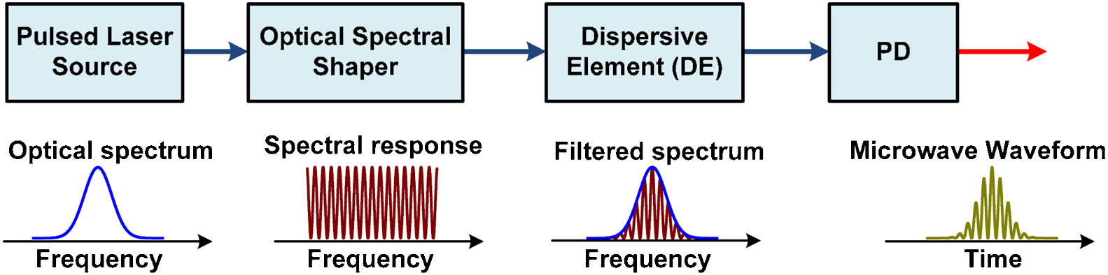
Figure 1.Schematic diagram for pulsed microwave waveform generation based on spectral shaping and FTTM.
The microwave pulse generated in Fig. 1, however, has a pedestal due to the square-law detection in the PD, so many low-frequency components appear in the electrical spectrum. To generate a background-free pulsed microwave signal without the unwanted low-frequency components, we propose a novel pulsed microwave signal generator, with its schematic diagram shown in Fig. 2, to realize the spectral shaping and FTTM with balanced photodetection. The proposed scheme consists of a mode-locked laser (MLL), a DGD element (DGDE), a DE, two PCs, a PBS, and a balanced photodetector (BPD). The MLL is used as the pulsed laser source. The DGDE, the two PCs, and the PBS operate jointly as an optical comb filter. To obtain the desired optical power transfer function, the polarization direction of the incident light fed into the DGDE is aligned through PC1 to have an angle of 45° relative to one principal axis of the DGDE. The DGDE introduces a DGD of between its two principal axes ( and ). If the field of the optical signal injected into the DGDE is , where is the angular frequency of the optical signal, the optical fields at the output of the DGDE along the two principal axes can be expressed as By adjusting PC2 to let one principal axis of the PBS have an angle of 45° to one principal axis of the DGDE, as shown in Fig. 2, the two output signals from the PBS are given as

Figure 2.Proposed scheme for background-free pulsed microwave signal generation. MLL, mode-locked laser; PC, polarization controller; DGDE, differential group delay element; DE, dispersive element; PBS, polarization beam splitter; BPD, balanced photodetector; OSC, oscilloscope; ESA, electrical spectral analyzer.
Based on Eqs. (5) and (6), the optical power transfer functions at the two PBS outputs are As can be seen, two optical comb filters having cosine power transfer functions are obtained, and the power transfer functions in Eqs. (7) and (8) are complementary to each other.
In order to introduce the same dispersion to the optical signals in Eqs. (5) and (6), a DE is inserted after the DGDE, considering that the DE has a polarization-independent linear response. This configuration releases the requirement of DEs in both branches to the BPD. The two output signals from the PBS are then sent to the BPD for balanced photodetection. If the optical power spectrum of the pulsed laser source is , according to Eq. (3), the output current of the BPD can be written as As can be seen from Eq. (9), a pulsed microwave signal centered at the frequency of is generated. The frequency of the obtained microwave signal can be tuned by changing the DGD () of the DGDE and/or the dispersion () of the DE. It is worth noting that there are no low-frequency components in Eq. (9), which indicates that the obtained microwave signal is background free. As a comparison, if single-end detection is performed, which is the case in a traditional spectral shaping and FTTM systems, the generated electrical signal should be
As can be seen, the signal contains both the microwave signal centered at and the low-frequency components representing the profile of the broadened pulse. Furthermore, the amplitude of the pulsed microwave signal in Eq. (9) is twice of that in Eq. (10), which means the power of the obtained microwave signal by balanced photodetection will be enhanced by 6 dB.
When the angle between the principal axis of the PBS and the DGDE has a mismatch (not exactly 45°), it can be proved theoretically that the low-frequency components can still be eliminated by balanced photodetection, and the RF signal amplitude is also doubled compared with that obtained by single-end detection. However, the power of the RF signal will become lower due to the angle mismatch.
Figure 3 shows the simulation results for the generation of a Gaussian-shaped microwave pulse using single-end detection and balanced photodetection. In Fig. 3(a), the waveform obtained by single-end detection is positive with a pedestal, while the waveform obtained by balanced detection [Fig. 3(b)] has both positive and negative parts. The peak-to-peak amplitude of the signal generated by balanced detection is also twice that obtained by single-end detection. In the electrical spectra shown in Fig. 3(c), high-frequency components centered at are generated for both single-end detection and balanced detection. However, strong low-frequency components appear in the spectrum generated by single-end detection, indicating very low energy efficiency, while the spectrum obtained by balanced photodetection has no low-frequency components. In addition, the spectral power at for balanced photodetection is 6 dB higher than that for single-end detection. These results confirm that a background-free pulsed microwave signal can be generated based on the proposed scheme, and the power of the obtained microwave signal is enhanced simultaneously.
Figure 3.Simulation results for the generation of a Gaussian-shaped microwave pulse. Waveforms generated by (a) single-end detection and (b) balanced detection; (c) shows the corresponding electrical power spectra.
3. EXPERIMENTAL RESULTS AND DISCUSSION
To further investigate the performance of the proposed scheme, a proof-of-concept experiment is carried out based on the setup shown in Fig. 2. An MLL (Calmar Laser) generates a short optical pulse train with a repetition of 10 MHz. The full width at half-maximum of the pulse is . Due to the lack of a tunable DGD or dispersive device, a polarization-maintaining fiber (PMF) and a single-mode fiber (SMF) are used. Different DGDs and dispersions are obtained by changing the length of the PMF and the SMF. To perform the balanced photodetection, a 40 GHz BPD (u2t BPDV2150R-VF-FP) is used. The optical spectra before and after the PBS are monitored by an optical spectrum analyzer with a resolution of 0.02 nm. In addition, the waveform and electrical spectrum of the generated microwave signal are observed through an oscilloscope and an electrical spectral analyzer, respectively.
First, a 6.5 m PMF () and a 7.8 km SMF () are used in the experiment. Figure 4(a) shows the optical spectrum before the PBS. The optical spectra measured at the two outputs (output1 and output2) of the PBS are shown in Fig. 4(b). As can be seen in Fig. 4(b), the cosine profiles are successfully imposed on the two optical power spectra with a wavelength spacing of 0.6 nm between adjacent peaks, and the two optical spectra are found to be complementary to each other. After FTTM in the SMF and the optical-to-electrical conversion at the BPD, the obtained pulsed microwave waveforms are shown in Fig. 5. Figure 5(a) shows the waveforms generated by single-end detections, which are obtained by sending the optical signal from output1 of the PBS into PD1 of the BPD, and by sending the signal from output2 of the PBS into PD2 of the BPD, respectively. Figure 5(b) shows the waveform obtained by balanced photodetection, which is actually the summation of the two waveforms in Fig. 5(a). As shown in Fig. 5, temporal oscillations with the period of are observed in all the waveforms. In Fig. 5(a), the waveform obtained by single-end detection at PD1 is a scaled version of the optical spectrum at output1 of the PBS, which has apparent pedestals. When balanced photodetection is enabled, a pulse having both positive and negative parts is obtained, and its amplitude (60 mV) is nearly twice that obtained by single-end detection (31 mV).
Figure 4.Optical spectra (a) before the PBS and (b) at the two outputs of the PBS.
Figure 5.Measured waveforms of the generated microwave pulses obtained by (a) single-end detection using the BPD and (b) balanced photodetection.
The electrical power spectra for the signals generated by single-end and balanced detection are shown in Figs. 6(a) and 6(b), respectively. In both Figs. 6(a) and 6(b), high-frequency components centered at 12.46 GHz are observed, which agrees well with the theoretical value calculated by . For single-end detection, very strong low-frequency components below 2 GHz are observed, as shown in Fig. 6(a). When balanced photodetection is performed, the low-frequency components are suppressed by 31.1 dB, and the spectral amplitude at 12.46 GHz is increased by 5.5 dB, which is very close to the theoretical result (6 dB). These experimental measurements confirm that a power-enhanced, background-free pulsed microwave signal is successfully generated.
Figure 6.Electrical power spectra of the pulsed microwave signals obtained by (a) single-end and (b) balanced detection.
The central frequency of the generated background-free microwave signal can be adjusted by either changing the length of the PMF or the length of the SMF. When the SMF is changed from 7.8 to 5.88 km (), the waveform and electrical spectrum of the generated background-free pulsed microwave signal are shown in Figs. 7(a) and 7(b), respectively. The obtained waveform has a temporal oscillation period of , and the amplitude is 69 mV. In the electrical spectrum, the central frequency of the obtained microwave signal is changed to 16.52 GHz, and the suppressed low-frequency components are 26.5 dB lower than the 16.52 GHz component. When the length of the PMF is changed from 6.5 to 12.4 m () while the SMF is still 7.8 km long, the obtained microwave waveform and electrical spectrum are shown in Figs. 7(c) and 7(d), respectively. In Fig. 7(c), the waveform has a temporal oscillation period of and its amplitude is 13.4 mV. In the electrical spectrum shown in Fig. 7(d), high-frequency components centered at 23.7 GHz are generated and the low-frequency components are 17.4 dB lower than the 23.7 GHz component.
Figure 7.Waveforms and electrical spectra of the pulsed microwave signals at (a) and (b) , and (c) and (d) , .
The stability of the proposed system is also investigated in the experiment. When the polarization-dependent devices (i.e., the DGDE and the PBS) are fixed on the platform and the room temperature is kept unchanged, the measured microwave waveforms can remain unchanged during a two-hour observation. However, when the temperature changes, the phase and amplitude of the obtained microwave signal will change slightly, which is mainly due to the length fluctuation and the polarization rotation in the SMF. Thus, if the polarization devices are well fixed and a temperature controller is used to stabilize the temperature, the proposed system is expected to achieve very high stability.
4. CONCLUSION
We have proposed and experimentally demonstrated a scheme for the generation of a background-free pulsed microwave signal based on spectral shaping and FTTM with balanced photodetection. In the proposed scheme, a DGDE, two PCs, and a PBS are used as the optical spectral shaper that has two outputs with complementary power transfer functions. Thanks to the balanced photodetection at the BPD, low-frequency components are removed and a background-free pulsed microwave signal is generated. In addition, the amplitude of the microwave signal obtained by balanced photodetection is doubled compared with that obtained by single-end detection. The principle of the proposed scheme is analytically analyzed and its performance is investigated by an experiment. For the generation of a pulsed microwave signal centered at 12.46 GHz, the low-frequency components are suppressed by more than 30 dB and the spectral power at 12.46 GHz is increased by 5.5 dB, compared with that obtained by single-end detection. By changing the DGD and/or the dispersion, the central frequency of the obtained background-free pulsed microwave signal can be tuned. The proposed pulsed microwave generator is simple and flexible, and can find applications in broadband wireless communications, radars, and electronic warfare systems.
References
[1] J. Capmany, D. Novak. Microwave photonics combines two worlds. Nat. Photonics, 1, 319-330(2007).
[2] J. P. Yao. Microwave photonics. J. Lightwave Technol., 27, 314-335(2009).
[3] M. H. Khan, H. Shen, Y. Xuan, L. Zhao, S. Xiao, D. Leaird, A. M. Weiner, M. Qi. Ultrabroad-bandwidth arbitrary radiofrequency waveform generation with a silicon photonic chip-based spectral shaper. Nat. Photonics, 4, 117-122(2010).
[4] J. P. Yao. Photonic generation of microwave arbitrary waveforms. Opt. Commun., 284, 3723-3736(2011).
[5] E. H. Bernhardi, M. Khan, C. G. H. Roeloffzen, H. A. G. M. van Wolferen, K. Worhoff, R. M. de Ridder, M. Pollnau. Photonic generation of stable microwave signals from a dual wavelength Al2O3:Yb3+ distributed feedback waveguide laser. Opt. Lett., 37, 181-183(2012).
[6] J. Chou, Y. Han, B. Jalali. Adaptive RF-photonic arbitrary waveform generator. IEEE Photon. Technol. Lett., 15, 581-583(2003).
[7] I. S. Lin, J. D. McKinney, A. M. Weiner. Photonic synthesis of broadband microwave arbitrary waveforms applicable to ultra-wideband communication. IEEE Photon. Technol. Lett., 15, 226-228(2005).
[8] H. Chi, F. Zeng, J. P. Yao. Photonic generation of microwave signals based on pulse shaping. IEEE Photon. Technol. Lett., 19, 668-670(2007).
[9] F. Zhang, X. Ge, S. Pan. Photonic generation of pulsed microwave signals with tunable frequency and phase based on spectral-shaping and frequency-to-time mapping. Opt. Lett., 38, 4256-4259(2013).
[10] H. Y. Jiang, L. S. Yan, Y. F. Sun, J. Ye, W. Pan, B. Luo, X. H. Zou. Photonic arbitrary waveform generation based on crossed frequency to time mapping. Opt. Express, 21, 6488-6494(2013).
[11] M. A. Muriel, J. Azana, A. Carballar. Real-time Fourier transformer based on fiber gratings. Opt. Lett., 24, 1-3(1999).
[12] J. McKinney. Background free arbitrary waveform generation via polarization pulse shaping. IEEE Photon. Technol. Lett., 22, 1193-1195(2010).
[13] M. Abtahi, J. Magne, M. Mirshafiei, L. A. Rusch, S. LaRochelle. Generation of power-efficient FCC-compliant UWB waveforms using FBGs: analysis and experiment. J. Lightwave Technol., 26, 628-635(2008).
[14] M. Abtahi, M. Dastmalchi, S. LaRochelle, L. A. Rusch. Generation of arbitrary UWB waveforms by spectral pulse shaping and thermally-controlled apodized FBGs. J. Lightwave Technol., 27, 5276-5283(2009).
[15] Y. Du, J. Zheng, L. Wang, H. Wang, N. Zhu, J. Liu. Widely-tunable and background-free ultra-wideband signals generation utilizing polarization modulation-based optical switch. IEEE Photon. Technol. Lett., 25, 335-337(2013).
[16] W. Li, L. X. Wang, M. Li, N. H. Zhu. Photonic generation of widely tunable and background-free binary phase-coded radio-frequency pulses. Opt. Lett., 38, 3441-3444(2013).


