
Peng Yuan, Jingui Ma, Yongzhi Wang, Jing Wang, Daolong Tang, and Liejia Qian. Pump phase transfer and its control in hybrid seeded optical parametric amplifiers[J]. High Power Laser Science and Engineering, 2014, 2(4): 04000e30
- High Power Laser Science and Engineering
- Vol. 2, Issue 4, 04000e30 (2014)
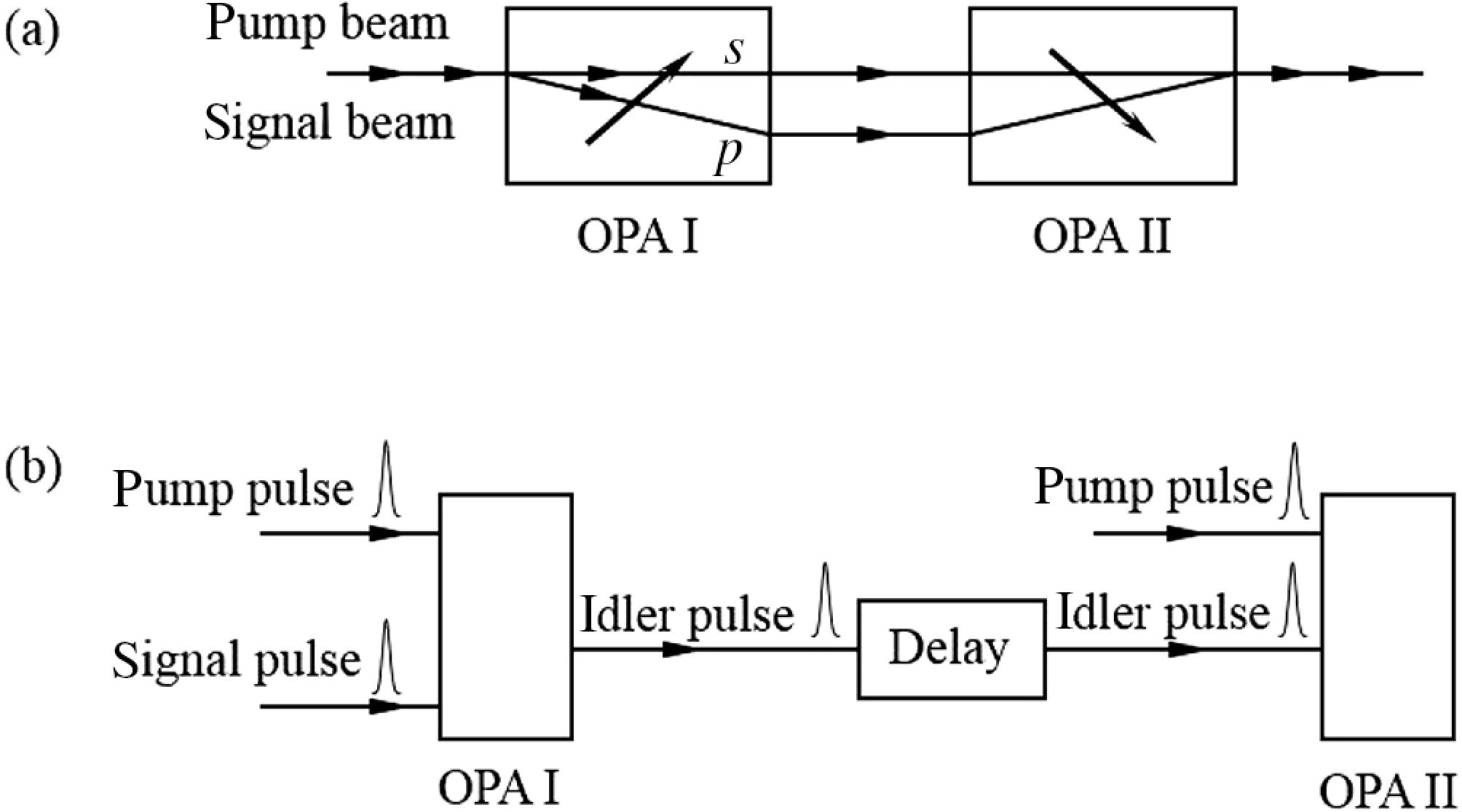
Fig. 1. Schematic of optimized OPA designs: (a) walk-off-compensating configuration; (b) hybrid seeding configuration (the two-stage OPAs are seeded by signal and idler waves, respectively).
![Calculated signal phase distortion and restoration in a two-stage OPA system. (a) The dotted line plots the initial phase modulation on the pump pulse. The solid line is the phase of the amplified signal from the first stage OPA. (b) The phase of the amplified signal from the second OPA stage which is seeded by the amplified signal from the first stage (conventional multistage OPA configuration). (c) The phase of the amplified signal from a hybrid seeded OPA with the condition . (d) The phase of the amplified signal (solid line) from a hybrid seeded OPA with the condition . The dotted line in (d) is the phase of the pump pulse after amplification. The nonlinear length [14], as an identification of the pump intensity, was fixed in the calculations to be for each stage.](/richHtml/hpl/2014/2/4/04000e30/img_2.gif)
Fig. 2. Calculated signal phase distortion and restoration in a two-stage OPA system. (a) The dotted line plots the initial phase modulation on the pump pulse. The solid line is the phase of the amplified signal from the first stage OPA. (b) The phase of the amplified signal from the second OPA stage which is seeded by the amplified signal from the first stage (conventional multistage OPA configuration). (c) The phase of the amplified signal from a hybrid seeded OPA with the condition  . (d) The phase of the amplified signal (solid line) from a hybrid seeded OPA with the condition
  . The dotted line in (d) is the phase of the pump pulse after amplification. The nonlinear length
  [14], as an identification of the pump intensity, was fixed in the calculations to be
  for each stage.
. (d) The phase of the amplified signal (solid line) from a hybrid seeded OPA with the condition . The dotted line in (d) is the phase of the pump pulse after amplification. The nonlinear length [14], as an identification of the pump intensity, was fixed in the calculations to be for each stage. Fig. 3. Beam patterns of the pump beam measured  after the crystal (used for Kerr-effect-induced spatial phase distortion): (a) in the linear propagation regime; (b) at high intensity (
 ). Beam patterns of the amplified signal from the first OPA stage measured at the focus: (c) in the walk-off plane; (d) in the no-walk-off plane. Amplified signal from the second OPA stage measured at the focus in the no-walk-off plane: when the overlap between the pump and idler beams was not optimized (e) and when it was optimized (f).
after the crystal (used for Kerr-effect-induced spatial phase distortion): (a) in the linear propagation regime; (b) at high intensity (). Beam patterns of the amplified signal from the first OPA stage measured at the focus: (c) in the walk-off plane; (d) in the no-walk-off plane. Amplified signal from the second OPA stage measured at the focus in the no-walk-off plane: when the overlap between the pump and idler beams was not optimized (e) and when it was optimized (f). Fig. 4. Measured beam profiles of the amplified signal from the hybrid seeded OPA. The dotted line plots the beam profile in the no-walk-off plane. The solid line is the beam profile in the walk-off plane after the spatial overlap between the pump and idler beams was optimized. The dashed line shows the beam profile in the walk-off plane when the pump–idler overlap was not optimized.
Fig. 5. (a) Measured pump pulse spectra before (dashed line) and after (solid line) the crystal (where self-phase modulation occurred). (b) Measured signal pulse spectra when the time delay between the idler and the pump was  (dashed line) and 0 (solid line), respectively.
(dashed line) and 0 (solid line), respectively. 
Set citation alerts for the article
Please enter your email address
© Copyright 2018-2021 | Chinese Laser Press. All Rights Reserved 沪ICP备15018463号-20