• Chinese Journal of Lasers
  • Vol. 48, Issue 20, 2007002 (2021)
Junyi Ouyang1、2, Zhongliang Li2、3、*, Teng Liu2、3, Nan Nan2、**, Xiaona Yan1, and Xiangzhao Wang2、3
Author Affiliations
  • 1College of Sciences, Shanghai University, Shanghai 200444, China
  • 2Laboratory of Information Optics and Opto-Electronic Technology, Shanghai Institute of Optics and Fine Mechanics, Chinese Academy of Sciences, Shanghai 201800, China
  • 3Center of Materials Science and Optoelectronics Engineering, University of Chinese Academy of Sciences, Beijing 100049, China
  • show less
    DOI: 10.3788/CJL202148.2007002 Cite this Article Set citation alerts
    Junyi Ouyang, Zhongliang Li, Teng Liu, Nan Nan, Xiaona Yan, Xiangzhao Wang. An Extended-Focus Optical Coherence Tomography System Based on Circular Dammann Grating[J]. Chinese Journal of Lasers, 2021, 48(20): 2007002 Copy Citation Text show less
    Schematic of an SSOCT system
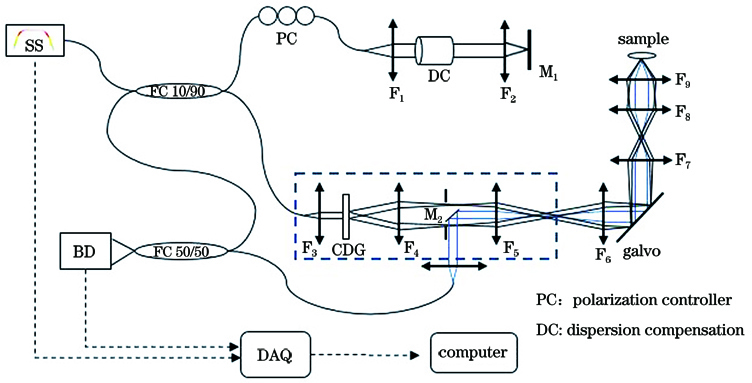
    Fig. 1. Schematic of an SSOCT system
    Schematic of a one-order CDG
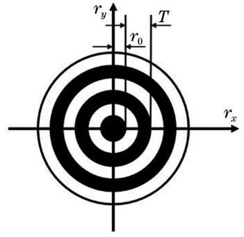
    Fig. 2. Schematic of a one-order CDG
    Energy distribution of the first order diffraction ring on the back focal plane of F4
    Fig. 3. Energy distribution of the first order diffraction ring on the back focal plane of F4
    Axial energy distributions of Bessel beam center spot at different distances from F5 back focal plane under different filtering conditions
    Fig. 4. Axial energy distributions of Bessel beam center spot at different distances from F5 back focal plane under different filtering conditions
    Graphic representations of δ(1/2)(x) and δ(1/2)(-x)
    Fig. 5. Graphic representations of δ(1/2)(x) and δ(1/2)(-x)
    Energy distributions of the first-order diffraction ring. (a) a=b; (b) a=-b
    Fig. 6. Energy distributions of the first-order diffraction ring. (a) a=b; (b) a=-b
    Relationship between duty ratio T0 and diffraction efficiency η
    Fig. 7. Relationship between duty ratio T0 and diffraction efficiency η
    Comparison of two CDG configurations. (a) Radial energy distributions of the first order diffraction ring; (b) axial energy distribution of central spot under the condition of CDG-A; (c) axial energy distribution of central spot under the condition of CDG-B; (d) normalized axial energy distributions of central spot
    Fig. 8. Comparison of two CDG configurations. (a) Radial energy distributions of the first order diffraction ring; (b) axial energy distribution of central spot under the condition of CDG-A; (c) axial energy distribution of central spot under the condition of CDG-B; (d) normalized axial energy distributions of central spot
    Illumination field at the sample position
    Fig. 9. Illumination field at the sample position
    Energy distribution of the first order diffraction ring
    Fig. 10. Energy distribution of the first order diffraction ring
    Axial point spread function
    Fig. 11. Axial point spread function
    Microbeads imaging. (a) Image of 2 μm microbeads; (b)--(d) lateral point spread functions in different regions
    Fig. 12. Microbeads imaging. (a) Image of 2 μm microbeads; (b)--(d) lateral point spread functions in different regions
    OCT images measured by the OCT system. (a) Fingernail; (b) multilayer white tape
    Fig. 13. OCT images measured by the OCT system. (a) Fingernail; (b) multilayer white tape
    Junyi Ouyang, Zhongliang Li, Teng Liu, Nan Nan, Xiaona Yan, Xiangzhao Wang. An Extended-Focus Optical Coherence Tomography System Based on Circular Dammann Grating[J]. Chinese Journal of Lasers, 2021, 48(20): 2007002
    Download Citation