
Brendan A. Reagan, Cory Baumgarten, Elzbieta Jankowska, Han Chi, Herman Bravo, Kristian Dehne, Michael Pedicone, Liang Yin, Hanchen Wang, Carmen S. Menoni, Jorge J. Rocca. Scaling diode-pumped, high energy picosecond lasers to kilowatt average powers[J]. High Power Laser Science and Engineering, 2018, 6(1): 01000e11
- High Power Laser Science and Engineering
- Vol. 6, Issue 1, 01000e11 (2018)
![Summary of diode-pumped, high energy/high average power, short pulse lasers. Demonstrated, diode-pumped, $\unicode[STIX]{x1D706}\approx 1~\unicode[STIX]{x03BC}\text{m}$ lasers producing ${>}10~\text{mJ}$ pulse energy at ${>}10~\text{Hz}$ repetition rate that are compressible to sub-10 ps duration are included. The energy scale is before compression, and the reference number of each laser is shown next to each.](/richHtml/hpl/2018/6/1/01000e11/img_1.gif)
Fig. 1. Summary of diode-pumped, high energy/high average power, short pulse lasers. Demonstrated, diode-pumped, $\unicode[STIX]{x1D706}\approx 1~\unicode[STIX]{x03BC}\text{m}$ lasers producing ${>}10~\text{mJ}$ pulse energy at ${>}10~\text{Hz}$ repetition rate that are compressible to sub-10 ps duration are included. The energy scale is before compression, and the reference number of each laser is shown next to each.
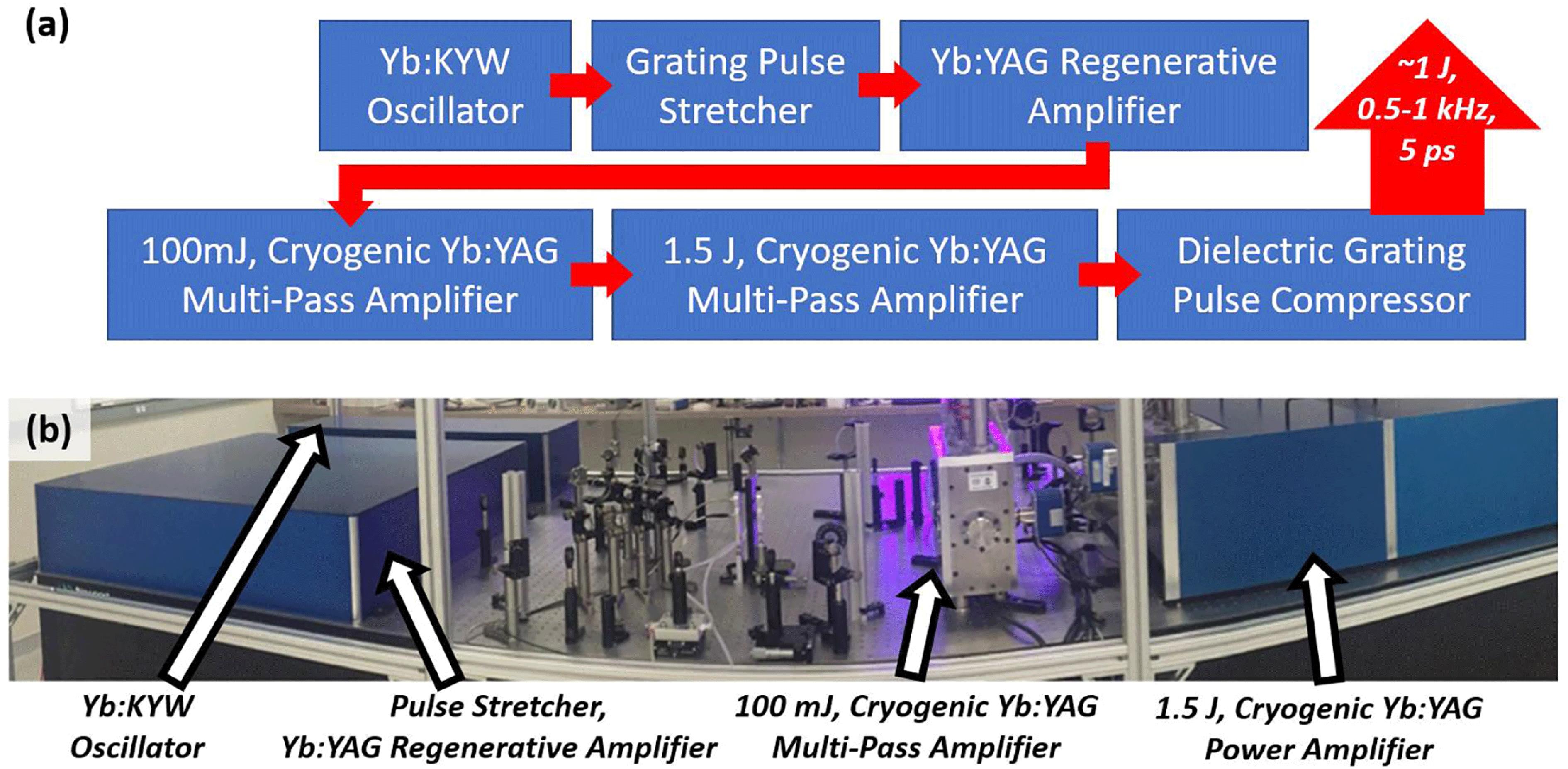
Fig. 2. (a) Laser system diagram. The output of a diode-pumped, mode-locked bulk Yb:KYW oscillator is stretched by a grating stretcher and amplified to the millijoule level by a Yb:YAG regenerative amplifier. These seed pulses are subsequently amplified by a chain of two high power cryogenic amplifiers, and are compressed in vacuum by a dielectric grating pair. (b) Panoramic photograph of the high energy, high average power laser.
Fig. 3. (a) Layout of the 500 Hz repetition rate, 100-mJ-level, cryogenic amplifier. (b) Measured pulse energy as a function of total pump energy at 500 Hz repetition rate. (c) Spectrum of the amplified pulses showing a bandwidth of 0.43 nm FWHM. (d) SHG autocorrelation of the compressed, 100 mJ pulses at 500 Hz repetition rate. The sech$^{2}$ fit shown corresponds to a pulse duration of 3.9 ps FWHM.
Fig. 4. (a) Measured pulse energy exiting the 100-mJ-level cryogenic amplifier at 1 kHz repetition rate. (b) 30 min continuous operation at 1 kHz. A mean energy of 67 mJ with RMS fluctuation of 0.6% was measured over this 1.8 million consecutive shots.
Fig. 5. (a) Layout of the high repetition rate, 1.5 J amplifier. (b) Photo of the enclosed amplifier, which occupies a table space of just over $1~\text{m}\times 0.5~\text{m}$ . $\unicode[STIX]{x1D706}/4$ : quarter waveplate, P: periscope, 6 kW: 60 bar laser diode stacks.
Fig. 6. (a) Measured laser pulse energy exiting the main amplifier at 500 Hz repetition rate as a function of combined pump energy. (b) Amplified pulse energy over 30 min of continuous operation at 500 Hz repetition rate. A mean energy of 1.4 J was measured with an RMS fluctuation of 0.75%. (c) M$^{2}$ measurement in two orthogonal directions of the amplified output producing 1.4 J at 500 Hz repetition rate. (d) Far-field beam image of the full power output.
Fig. 7. (a) Schematic of the Mach–Zehnder interferometer used to make the thermal wavefront measurements. Millijoule-level, $\unicode[STIX]{x1D706}=1.03~\text{m}$ pulses produced by a Yb:YAG regenerative amplifier are magnified and beamsplit with equal magnitude. The probe arm is made to make a single pass through the Yb:YAG amplifier disk under test (where one pass is defined at transmitting through the active region of the active mirror, reflecting off the highly reflective (HR) face and transmitting again through the active region). The reference beam is sent through a delay line of length equal to the probe arm before the two beams are recombined by a second beamsplitter. An $f=680~\text{mm}$ convex lens is used to image the plane of the amplifier onto a CMOS camera. The camera used in the interferometer is mounted on a translation stage that allows for precise determination of the location of the focus of the convex lens.
Fig. 8. Interferograms obtained for average pump power of (a) 0.63, (b) 0.70, (c) 1.04, and (d) 1.53 kW, respectively. (e–h) Calculated thermally deformed wavefront maps from these interferograms. A reference wavefront measured with no pump power was subtracted in each case, resulting in only the thermal contribution. All maps are plotted on the same scale. (i–l) 3D surface plots of the wavefronts.
Fig. 9. Thermal focusing power as a function of average pump power calculated from the interferograms of Figure 8 (circles). Also shown are the thermal lens strengths measured from the displacement of the focus (squares). Straight lines connect successive points to guide the eye. At the highest thermal load, positive focal lengths of 30 and 41 m are obtained for the horizontal and vertical axes, respectively.
Fig. 10. Measured amplified pulse energy at 1 kHz repetition rate as a function of total pump energy. The pump pulse duration was 0.5 ms, and the amplifier was seeded with about 65 mJ pulses (see Figure 4 ). At the maximum pump energy, an amplified pulse energy of 1 J was obtained with 25% optical-to-optical efficiency.

Set citation alerts for the article
Please enter your email address
© Copyright 2018-2021 | Chinese Laser Press. All Rights Reserved 沪ICP备15018463号-20