Zhidong Chen, Xinzhu Sang, Hui Li, Yuan Wang, Linmin Zhao, "Ultra-lightweight and wide field of view augmented reality virtual retina display based on optical fiber projector and volume holographic lens," Chin. Opt. Lett. 17, 090901 (2019)
Copy Citation Text
A novel see-through virtual retina display (VRD) system is proposed in this Letter. An optical fiber projector is used as the thin-light-beam source, which is modified from a laser scan projector by separating the laser sources and the scan mechanical structure. A synthetic aperture method is proposed for simple, low-cost fabrication of a volume holographic lens with large numerical aperture. These two key performance-enhanced elements are integrated into a lightweight and ordinary-glasses-like optical see-through VRD system. The proposed VRD system achieves a weight of 30 g and a diagonal field of view of 60°.
Recently, virtual reality (VR) and augmented reality (AR) have attracted significant interest, especially as they have potential for a broad range of consumer applications[1]. In particular, near-eye displays, also known as head-mounted displays (HMDs), have been developed, which provide device wearers with an excellent VR/AR experience. The near-eye display solution directly affects the HMD device configuration and the user experience. In a near-eye AR device, this optical solution creates a digital virtual image appearing at a comfortable distance from the viewer. To enable AR applications, the invention of a compact lightweight optical see-through AR display engine with ideal optical performance characteristics, such as a wide field of view (FOV), full-color visualization, and high resolution, without vergence-accommodation conflict (VAC), is very essential.
In an optical see-through AR display engine, the optical combiner plays a core role. It combines the physical world view and the digital information. There are different kinds of optical combiners, such as a flat beam splitter, a curved or freeform surface with beam splitting coating, and a holographic optical element (HOE) or waveguide. In these combiners, the HOE and waveguide have the potential to make AR devices close to ordinary glasses[2–4]. Although some AR devices in the form of glasses based on an HOE or waveguide have been made, their volume and weight are still not ideal. As a daily-wear device, the volume of the components integrated into the AR glasses should be minimized the most. However, the currently existing head-mounted AR devices still retain many components such as display panels, batteries, and circuit board, which inevitably increase the burden of the head. In this Letter, apart from using HOE as the optical combiner, we also propose an optical fiber projector to remove the optics-independent components from AR glasses, further reducing the weight to 30 g.
Another problem that should be solved in near-eye display is VAC. VAC forces the viewer’s brain to unnaturally adapt to conflicting cues and increases fusion time of binocular imagery, while decreasing fusion accuracy[5]. Light-field[6,7], multi-focal plane[8], vari-focal plane[9], holographic[10–12], and Maxwellian view[13] displays are five major solutions developed to solve the VAC problem. Among those solutions, the Maxwellian view display, also known as virtual retina display (VRD) technology, has the advantages of zero resolution loss and low computation cost. In this Letter, a prototype based on VRD technology was built to support the focus-free cue.
Sign up for Chinese Optics Letters TOC. Get the latest issue of Chinese Optics Letters delivered right to you!Sign up now
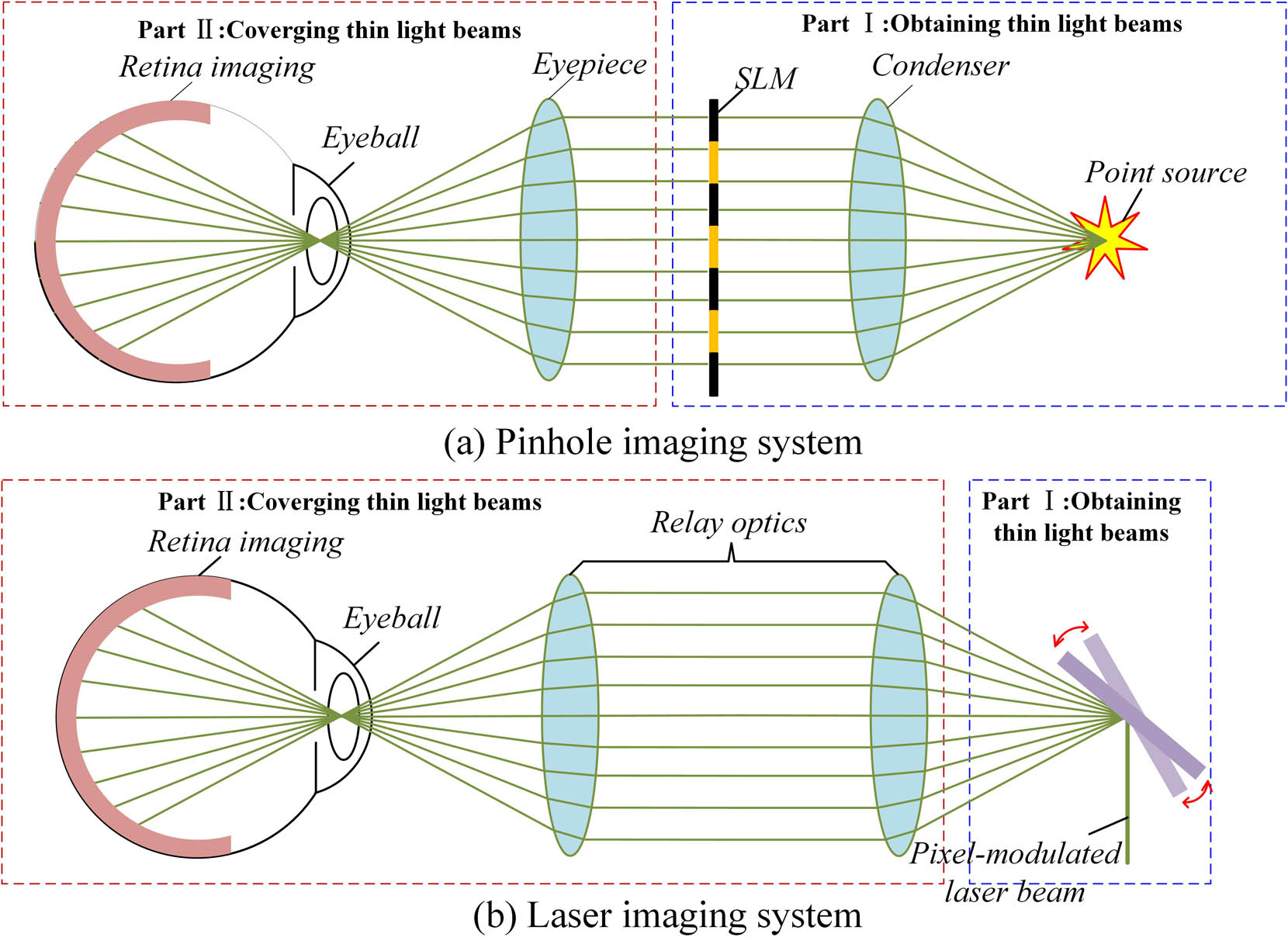
In VRD, which was first proposed by Ando et al.[14], the depth of focus (DOF) is extended by projecting a very thin bundle of rays from each field of the display to focus on the retina through a small area on the pupil. In the context of geometric optics, this method extends the DOF of the near-eye imaging system by essentially reducing the imaging-system aperture diameter. A VRD system consists of two parts: one obtains thin light beams and the other converges the thin beams at the center of the eyeball pupil.
The basic principles of a VRD system are shown in Fig. 1. According to how the image is generated, a standard VRD system can be constructed in one of two forms, i.e., with a pinhole or laser image display. In a pinhole imaging system, shown in Fig. 1(a), an eyepiece converges the parallel rays emitted from the aperture of the spatial light modulator (SLM) on the center of the pupil entrance of the observing eye. The collimated rays are produced by a point source and are then collimated by a condenser lens. The target images are loaded on the SLM, and the intensity of each ray is modulated by the pixel through which it passes[15]. In a laser image display system, shown in Fig. 1(b), a pixel-modulated laser beam is raster-scanned two-dimensionally by a scanning device, such as a two-axis micro-electromechanical-system (MEMS) mirror. The scanning laser beam is synchronized to a digital image source and is also converged at the pupil center by relay optics consisting of two lenses[16]. In both the pinhole and laser imaging systems, the pixel-modulated rays are sufficiently thin and collimated. These thin rays pass through the pupil and reach the retina without engaging the focusing function of the eye lens, forming a sharp image on the retina.
Figure 1.Principles of VRD systems: (a) pinhole and (b) laser imaging systems.
In order to focus the thin light beam on the center of the eyeball pupil, optical elements such as convex lens, concave mirror, and HOE, that have positive optical power should be used in VRD systems. A convex lens or lens group is commonly used as the beam convergence element in a VR-VRD system as shown in Fig. 1, and correspondingly, in an AR-VRD system, a half-concave mirror[17] or HOE[18] is applied to converge the beams. Moreover, a half-concave mirror or HOE can also make the physical light pass through, so that these two elements can also be used as the optical combiner to combine the view of the virtual image with that of a real-world scene.
Regardless of the particular VRD system type, the bundled thin-ray source and the ray-converging element are two indispensable parts. In this Letter, we improve these two key parts of the VRD system to realize an ordinary-glasses-like AR-VRD prototype that is ultra-lightweight, while also supporting a focus-free cue. The architecture of our proposed AR-VRD system is shown in Fig. 2. The bundled thin-ray source we used is a fiber projector, which is an improvement on the laser imaging technique for producing a thin light beam, through use of an optical fiber to separate the laser sources and the scan mechanical structure. The ray-converging element in this proposed method is an HOE, more specifically a volume holographic lens (VHL). An HOE is an optical element that is produced using holographic imaging processes or principles. It can achieve different optical functions such as a lens, filter, beam splitter, or diffraction grating by different fabrication methods[19]. The spectral and angular Bragg selectivity of the HOE makes it particularly well-suited for a combiner, providing both good see-through quality and good quality of the projected image. The advantages of HOE are that its thickness is only a few to tens of microns, and its transmission and diffracted efficiency can reach up to 90%. The HOE adopted in our proposed system is a VHL, which is commonly fabricated by the interference of a diverging wave and a converging wave. In this Letter, the fabrication method is modified via a synthetic aperture method, which allows fabrication of a VHL with a larger numerical aperture () at low cost. By this improved method, a VHL with a focal length of 20 mm and an effective area of 24 mm width by 18 mm height is achieved. With a larger , the VHL can realize a wider FOV AR-VRD system.
In our proposed AR-VRD display system, we use an MEMS-based projector as our image source. The projector architecture consists of one red (R), one green (G), and one blue (B) laser, each with a lens near the laser output that collects the light from the laser and provides a beam with very low at the output. The output light from the three lasers is then combined into a single white beam by dichroic elements. Note that, in the original projector design, the combined beam is directly cast on an MEMS mirror for scanning and image production. In the proposed system, however, an MEMS-based projector (Microvision, Inc.) is modified to act as a fiber laser projector. The scanning frequencies of the MEMS mirror in the modified MEMS-based projector are 26,000 Hz at the fast axis and 1400 Hz at the slow axis, which can produce an image with a resolution of and a display reflash rate of 60 Hz.
The modified architecture of the fiber projector is shown at the bottom of Fig. 2. The intensities of the RGB laser diodes are modulated by the laser diode controller according to the received image signal. The pixel-modulated light is coupled into a single-mode optical fiber. The optical fiber can transmit the pixel-modulated light over a long distance. The core diameter of the transferred fiber is μ, and the is 0.12. A collimator is located at the end of the optical fiber. The optical simulation of the collimator is shown in Fig. 3. It is consisted of two lenses, and their focus lengths are 5.0 and 7.5 mm, respectively. The two lenses combine to adjust the diameter and the divergence angle of the light emitted from the optical fiber. After following transfer by the optical fiber, as shown at the top of Fig. 2, the modulated light is cast on the MEMS mirror, with two-dimensional scanning being performed to produce a sharp laser image. Through this transformation, the components such as laser diodes, dichroic mirrors, batteries, and circuit boards can be moved from AR glasses to a handheld device. So, we achieve a tiny optical fiber projector that can produce thin light beams and that does not occupy excessive space on the AR glasses.
Figure 3.Optical simulation of the fiber collimator.
The optical fiber projector projects the collimated light beams on the modified VHL, which can converge the light beams from the projector at the center of the eyeball pupil. The material of the VHL is photopolymer. When the photopolymer is exposed to two coherent waves, the two waves will interfere and form interference fringes in the photopolymer. The interference fringes can realize some specific optical functions and can be reserved in the photopolymer. The functionality and proposed fabrication method of the VHL in this Letter are shown in Fig. 4. The interference fringes are generated by a diverging wave and a converging wave. After the VHL is successfully fabricated by these two waves, when the VHL is illuminated by an off-axis spherical wave with a diverging angle of , as shown in Fig. 4(a), it generates a signal wave, which is a converging spherical wave having a focus point at the center of the eye lens. The VHL focal length is equal to the distance between the VHL and the center of the eye lens. The view angle of this system is given as where the is the VHL NA, and is the effective aperture. When is fixed, must be as large as possible to obtain a wide FOV. A wider FOV can give the user a stronger AR experience. However, generating this kind of converging spherical wave with an optical system is a challenge, as such a system must have a large and large , and such an optical system is difficult and expensive to fabricate. The previously reported AR-VRD system, utilizing an HOE as a combiner, had an FOV of less than [14]. The FOV of those systems is far less than the normal viewing of the physical world by the human eye.
Figure 4.(a) Synthetic aperture method for VHL fabrication and VHL functionality. (b) Separation of converging spherical wave into several sub-wavefronts. (c), (d) Stepwise recording method.
To address these problems and fabricate a VHL with large and , we implement the developed synthetic aperture method and further propose a stepwise recording method, which are shown in Figs. 4(b) and 4(d). In this approach, the converging spherical wave is separated into several sub-wavefronts, as shown in Fig. 4(b). The of each sub-wavefront is smaller than that of the complete converging spherical wave; thus, it can be produced by a simple optical system with reduced .
In the traditional recording method[20], a VHL is fabricated in one step, whereas in our proposed method, the recording procedure is separated into several steps. A mask is used to block the non-recorded area from exposure. In the specific procedure performed in this study, the entire signal wave was divided into four sub-wavefronts, and we used four recordings to complete the VHL fabrication. Hence, a cheap lens with , , and was used to obtain a VHL with , , and an effective aperture with 24 mm width and 18 mm height.
The recording optical system to fabricate the VHL is shown in Fig. 5. In this demonstration system, a G single-frequency laser with 532 nm wavelength was used as the wave source. In the proposed setup, a polarizer, an objective lens, a beam splitter, two collimating lenses, and some mirrors are used so that the laser beam is split into two expanded and collimated linearly polarized beams. After the beams pass through different lenses, they form a diverging reference wave and a converging signal wave. The HOE is divided into four parts by a mask with an aperture of 12 mm width and 9 mm height. In the different recording steps, the signal wave must be adjusted, so that the signal waves produced in different recording steps converge at the same point. A motorized XY stage is used to load and move the HOE, making sure that each exposure area does not overlap. Note that, although the HOE was monochromatic G in our demonstration, fabrication of multicolor HOEs has been reported[21]. Thus, it will be possible to fabricate a full-color HOE for full-color AR-VRD glasses in the near future.
The optical parameter of the prototype is listed in Table 1, and the manufactured prototype is shown in Fig. 6. It is apparent that the AR-VRD prototype appearance is close to that of ordinary glasses. The total weight of the prototype is just 30 g, which is within the weight range of normal glasses. The prototype was constructed using components from a commercial mobile phone with an MEMS projector. In this form, it is confirmed that all the optics-independent components can be moved from AR glasses to a handheld device. The AR results obtained using the manufactured prototype are shown in Fig. 7. It was confirmed that the long DOF of the VRD system, which could focus on either a near or distant scene, provided a clear view of the virtual image, as demonstrated in Figs. 7(a) and 7(b), respectively. However, as the stepwise recording method was used, the optical recording system should be carefully adjusted to prevent the discontinuity in the observed digital image. Figure 7(c) is an AR scene that illustrates the FOV of the proposed AR-VRD system. It can be shown that the proposed system also suffers from the distortion problem: a rectangular image is stretched into a trapezoid. However, this distortion problem can be corrected by imaging processing. To illustrate the FOV of the system, a white paper and a physical tape were located 20 cm from the camera. The tape on the paper indicated that the effective width of the projected image was 21 cm. Therefore, the horizontal FOV was 2arctan [21/(2 × 20)] = 55.4°. Considering the vertical direction, the diagonal FOV of the proposed system reaches 60°, so it is a wide FOV design[22].
Parameter
Specification
FOV
60° diagonal
Eyebox
<1mm
Eye relief
20 mm
Projector resolution
1280×720
Weight
30 g
Table 1. Optical Performance of the Proposed System
In conclusion, this Letter reports successful reduction of the volume of the thin-light-beam source in a VRD system through the proposed optical fiber projector, as well as achievement of a VHL with increased via the proposed low-cost synthetic aperture method to improve the view angle. Hence, a lightweight and wide FOV AR-VRD prototype was developed. Moreover, a full-color prototype will be implemented in the near future. The AR-VRD prototype is an ordinary-glasses-like HMD system, so the proposed method may have great potential as popular smart glasses. A system with a wider FOV can be manufactured by using more recordings. However, although a wider FOV can be achieved and the depth cue can be supported in this proposed system, an eye must locate at a specified narrow viewing area to observe a complete digital image due to the tiny diameter of the scanning beam. This character of the VRD system limits the rotating range of the observing eye. The eyebox enlarged method proposed by Kim and Park[12] can be used to address this problem in the following work.