
Xiang Ma, Shuang Zheng, Jia Liu, Quanan Chen, Qiaoyin Lu, Weihua Guo, "Design of a single-mode directly modulated orbital angular momentum laser," Chin. Opt. Lett. 19, 081401 (2021)
- Chinese Optics Letters
- Vol. 19, Issue 8, 081401 (2021)
Abstract
Keywords
1. Introduction
With the exponentially growing demand of data traffic capacity, orbital angular momentum (OAM)-carrying beams have attracted great interests for its topological helical phase fronts. OAM has been considered as an additional degree of freedom of a photon or light beam having the potential to obtain greater information capacity and can be widely applied into photonic integrated technologies[
Microcavities such as microdisks, microrings and microcylinders, supporting whispering gallery modes (WGMs), are normally used to generate OAM beams[
We have put forward a high-speed directly modulated cylindrical vector (CV) beam laser and demonstrated it experimentally[
Sign up for Chinese Optics Letters TOC. Get the latest issue of Chinese Optics Letters delivered right to you!Sign up now
2. Device Design and Theory
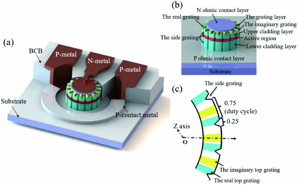
Figures 1(a) and 1(b) show the schematic structures of the single-mode high-speed directly modulated OAM beam laser. The detailed distributions of the gratings are shown in Fig. 1(c). From top to bottom, the device structure includes the N ohmic contact layer, the grating layer, the upper cladding layer, the active region, the lower cladding layer, the P ohmic contact layer, and the substrate.
![]()
Figure 1.(a) Schematic structure of the fabricated single-mode high-speed directly modulated OAM beam laser; (b) structure of the laser; (c) distribution of the gratings.
To strengthen the interaction of the top gratings and WGMs of the cavity, a thin upper cladding layer is set. N-I-P structure is adopted to decrease the resistance of the laser. The active region includes five compressively strained quantum wells sandwiched between the upper and lower 100 nm optical confinement layers with the same quaternary material. The thickness of every quantum well and barrier is 6 nm and 10 nm, respectively. An InGaAlAs/InP wafer with high differential gain grown on a semi-insulating InP substrate is used for the laser which is easier to realize high-speed modulation. To improve the current injection efficiency, proton is implanted into the P-doped lower cladding layer so as to form a cylinder area with high resistance right below the active region as shown in Fig. 2. With the ion implanted region, the high-order radial WGMs would be inhibited as well. To radiate travelling-wave mode with helical phase fronts, an imaginary part index modulation is introduced to the top grating.
![]()
Figure 2.Cross section of the modelling of the single-mode OAM laser.
Different from the CV beam laser, the cavity of the OAM beam laser here is a microcylinder added with two types of second-order gratings on the top called the top gratings. In this case, the top gratings and the side gratings will not have a symmetry plane any more. The top gratings contain the real part and the imaginary part modulation of the mode refractive index[
The cross section of the theoretical model of the OAM beam laser with simulated parameters is shown in Fig. 2 in detail. Outer radii of the N-ohmic contact layer and the cavity are 4.5 and 6 µm, respectively. With the high-resistance ion implantation region, the injected carriers will overlap with mode area of the WGMs adequately and the path of the current flow is pointed out in Fig. 2. An imaginary part of the refractive index is added to the center of the active region on behalf of some absorption loss coming from the N ohmic contact.
![]()
Figure 3.Typical distributions of the major electrical field components (a) Er and (b) Eφ of the WGMs in the cross section of the microcylinder cavity.
When the side grating is etched on the periphery of the microcylinder cavity, it would interact mainly with
In this case, the lasing mode selected by the side grating is a standing-wave mode with little corresponding standing-wave emission. Therefore, another mechanism is introduced for emitting travelling-wave field.
Similar to the CV beam laser, a top grating is used for efficient surface-emission. To form travelling-wave emission, the top grating should break the symmetry of the previous cavity with the side grating. The top gratings here include the real part and the imaginary part, which can modulate the real and imaginary parts of the mode refractive index, respectively. The number of the period of the top gratings is
From Eqs. (1) and (2), we can conclude that
The side grating will introduce serious scattering loss for all WGMs except one mode with
It is proved that the introduced refractive index modulation for the real part can be 0.2 µm-depth etched InP and for the imaginary part can be 45 nm-thickness deposited absorbing metal material germanium (Ge) with the finite element method[
3. Simulation and Discussion
The three-dimensional (3D) finite-difference time-domain (FDTD) method[
The microcylinder cavity interacted with only the side grating is analyzed first using 3D-FDTD method. The number of the grating periods
![]()
Figure 4.(a) Q factors of WGMs of the cavity added with only the side grating versus the azimuthal mode number; electrical field distributions of (b) the symmetrial mode and (c) the anti-symmetrical mode.
Then, we simulate the cavity added with both the side grating and the complex top gratings. From the above analysis, when the top gratings are added onto the microcylinder, the cavity will not have the symmetry plane any more. Therefore, in the simulation, the symmetry boundary conditions should not be used in this case. When
![]()
Figure 5.Spectral distribution of the TE WGMs of the OAM laser with l = − 1.
The near-electric-field intensity distributions of the lasing modes with
![]()
Figure 6.Near-field intensity distributions of the laser above the top grating, where the period number of the side grating N = 86 and that of the top grating M = 85. From the top to bottom row are three cases: (a) both the real and the imaginary grating, (b) only the real grating, and (c) only the imaginary grating are added to the microcylinder cavity and serve as the top grating.
The far-field intensity distributions and phase patterns of the OAM beam lasers above the top gratings in the vertical direction simulated by 3D FDTD method are shown in Figs. 7(a) and 7(b). Different orders
![]()
Figure 7.(a) Simulated far-field intensity and (b) phase pattern in the propagating direction of the near-field of the OAM beam laser. Various orders of −2, −1, 0, 1, and 2 from left to right are displayed.
The field pattern and spiral pattern of the radiated emission can be modulated by the difference of the period numbers between the side grating (
Noting that, to obtain a travelling-wave wavefront, N-pad metal cannot have a symmetrical boundary with the side grating.
The OAM beam laser can be easily realized at any wavelength by designing the period number of the gratings. The laser can also be realized with transverse magnetic (TM) WGMs with tensile-strained quantum wells, while the emission would be azimuthally polarized.
The characteristics of the OAM beam laser are analyzed by solving the transient multi-mode rate equations[
| Parameter | Value |
|---|---|
| Active region thickness (nm) | 48 |
| Microcylinder diameter (µm) | 12 |
| Current injection width (µm) | 1.5 |
| Nonlinear gain saturation factor ( | 2 |
| Material gain parameter ( | 2524 |
| Dominant mode | 5100 |
| Transparent carrier density ( | 2 |
| Optical confinement factor | 0.1 |
| Group index | 3.6 |
| Internal loss of active region ( | 20 |
| Surface recombination velocity | 5 |
| Linear recombination coefficient ( | 1 |
| Bimolecular recombination coefficient ( | 1 |
| Auger recombination coefficient ( | 3.5 |
| Spontaneous emission coefficient | 0.01 |
| Current injected into the active region (mA) | 10 |
| Current injection efficiency | 0.8 |
Table 1. Parameters used in the simulation
Here, the dominant mode (Q factor is about 5100 in Fig. 5) and other adjacent WGMs are considered in the simulation. In order to make the simulation reliable, actually measured gain parameters are used.
The upward emission takes a ratio of about 30% of the total emitted power. The calculated L-I curves are presented in Fig. 8(a), where the upward emitted power has a slope efficiency of 0.142 mW/mA. The threshold current is about 0.766 mA. Therein the linear recombination, spontaneous emission, Auger recombination, surface recombination, and current leakage have contributions of 0.093, 0.2265, 0.1897, 0.1543, and 0.1025 mA, respectively.
![]()
Figure 8.(a) L-I curves at the wavelength of 1310 nm, where both the total output power and the upward part are shown; (b) small signal modulation response of the OAM beam laser at different bias currents.
The small signal modulation response of the laser under different driving currents is simulated with the results shown in Fig. 8(b). As can be seen, the 3 dB bandwidth of the laser can reach about 20 and 29 GHz at the current injection of 4 and 8 mA, respectively.
4. Summary
In summary, we have theoretically and numerically demonstrated a new design of directly modulated single-mode OAM beam laser. The top gratings including the real part and the imaginary part modulation scatter the WGMs unidirectionally circulating only in clockwise or counterclockwise direction. Meanwhile, the side grating can select a radially polarized standing mode as the lasing mode with little scattering loss. Then an asymmetrical N-pad metal on the top of the microcavity is used for current injection. With the cooperation of the gratings, the OAM beam laser can work with single-mode stably and emit radially polarized emissions vertically. The OAM beam laser can be realized at any wavelength bands and firstly realized with high-speed direct modulation in order to satisfy the applications in optical communications.
References
[1] L. Allen, M. W. Beijersbergen, R. J. C. Spreeuw, J. P. Woerdman. Orbital angular momentum of light and the transformation of Laguerre-Gaussian laser modes. Phys. Rev. A, 45, 8185(1992).
[2] J. Wang, J. Y. Yang, I. M. Fazal, N. Ahmed, Y. Yan, H. Huang, Y. Ren, Y. Yue, S. Dolinar, M. Tur, A. E. Willner. Terabit free-space data transmission employing orbital angular momentum multiplexing. Nat. Photon., 6, 488(2012).
[3] G. M. Terriza, J. P. Torres, L. Torner. Twisted photons. Nat. Phys., 3, 305(2007).
[4] A. Mair, A. Vaziri, G. Weihs, A. Zeilinger. Entanglement of the orbital angular momentum states of photons. Nature, 412, 313(2001).
[5] C. Zhang, F. Pang, H. Liu, L. Chen, J. Yang, J. Wen, T. Wang. Highly efficient excitation of LP01 mode in ring-core fibers by tapering for optimizing OAM generation. Chin. Opt. Lett., 18, 020602(2020).
[6] T. Lin, A. Liu, X. Zhang, H. Li, L. Wang, H. Han, Z. Chen, X. Liu, H. Lü. Analyzing OAM mode purity in optical fibers with CNN-based deep learning. Chin. Opt. Lett., 17, 100603(2019).
[7] M. Scaffardi, M. N. Malik, E. Lazzeri, G. Meloni, F. Fresi, L. Poti, N. Andriolli, I. Cerutti, C. Klitis, L. Meriggi, N. Zhang, M. Sorel, A. Bogoni. A silicon microring optical 2 × 2 switch exploiting orbital angular momentum for interconnection networks up to 20 Gbaud. J. Lightwave Technol., 35, 3142(2017).
[8] J. Zhang, C. Z. Sun, B. Xiong, J. Wang, Z. B. Hao, L. Wang, Y. J. Han, H. T. Li, Y. Luo, Y. Xiao, C. Q. Yu, T. Tanemura, Y. Nakano, S. M. Li, X. L. Cai, S. Y. Yu. An InP-based vortex beam emitter with monolithically integrated laser. Nat. Commun., 9, 2652(2018).
[9] R. Li, X. Feng, D. Zhang, K. Cui, F. Liu, Y. D. Huang. Radially polarized orbital angular momentum beam emitter based on shallow-ridge silicon microring cavity. IEEE Photon. J., 6, 2200710(2014).
[10] X. Cai, J. Wang, M. J. Strain, B. Johnson-Morris, J. Zhu, M. Sorel, J. L. O’Brien, M. G. Thompson, S. Yu. Integrated compact optical vortex beam emitters. Science, 338, 363(2012).
[11] H. Li, D. B. Phillips, X. Wang, Y. D. Ho, L. Chen, X. Zhou, J. Zhu, S. Yu, X. Cai. Orbital angular momentum vertical-cavity surface-emitting lasers. Optica, 2, 547(2015).
[12] P. Miao, Z. Zhang, J. Sun, W. Walasik, S. Longhi, N. M. Litchinitser, L. Feng. Orbital angular momentum microlaser. Science, 353, 464(2016).
[13] X. Ma, Q. A. Chen, Q. Y. Lu, W. H. Guo. Grating assisted microcylinder surface-emitting laser. J. Lightwave Technol., 34, 4999(2016).
[14] X. Ma, S. Zheng, Q. Chen, S. Tan, P. Zhang, Q. Lu, J. Wang, W. Guo. High-speed directly modulated cylindrical vector beam laser. ACS Photon., 6, 3261(2019).
[15] L. Feng, Y.-L. Xu, W. S. Fegadolli, M.-H. Lu, J. E. B. Oliveira, V. R. Almeida, Y.-F. Chen, A. Scherer. Experimental demonstration of a unidirectional reflectionless parity-time metamaterial at optical frequencies. Nat. Material., 12, 108(2013).
[16] Y.-D. Yang, Y.-Z. Huang. Symmetry analysis and numerical simulation of mode characteristics for equilateral-polygonal optical microresonators. Phys. Rev. A, 76, 023822(2007).
[17] W. B. Zimmerman. Multiphysics Modeling with Finite Element Method(2006).
[18] A. Taflove, S. C. Hagness. Computational Electrodynamics: the Finite-Difference Time-Domain Method(2005).
[19] W. H. Guo, W. J. Li, Y. Z. Huang. Computation of resonant frequencies and quality factors of cavities by FDTD technique and Padé approximation. IEEE Microwave Wireless Compon. Lett., 11, 223(2001).
[20] L. A. Coldren, S. W. Corzine, M. L. Mashanovitch. Diode Lasers and Photonic Integrated Circuits(2012).


Set citation alerts for the article
Please enter your email address

© Copyright 2018-2021 | Chinese Laser Press. All Rights Reserved 沪ICP备15018463号-20