Author Affiliations
1Southern University of Science and Technology, Department of Materials Science and Engineering, Shenzhen, China2Southern University of Science and Technology, Shenzhen Institute for Quantum Science and Engineering, Shenzhen, China3Southern University of Science and Technology, Institute for Applied Optics and Precision Engineering, Shenzhen, China4Southern University of Science and Technology, Guangdong Provincial Key Laboratory of Functional Oxide Materials and Devices, Shenzhen, Chinashow less
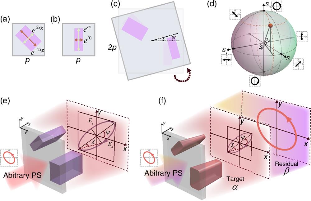
Fig. 1. Design concept of the metasurface polarizers. (a) A 45 deg counterclockwise rotated meta-atom with birefringence in a square lattice of period . The phase retardation in different axes depends on the output PS’s ellipticity angle . (b) A meta-atom, which is equivalent to a half-wave plate in a square lattice of period . (c) The unit cell of a metasurface polarizer consists of two above-mentioned meta-atoms, which has a period. The two meta-atoms fill the diagonal position and the rotation angle of these combinations depends on the output PS’s main axes angle . (d) Arbitrary PS on the Poincaré sphere can be described by the two parameters and . (e) The schematic illustration of an ideal metasurface polarizer. Under the pumping of arbitrary PS, the metasurface polarizer can completely convert it into the target PS . (f) The schematic illustration of the imperfect metasurface polarizer. Only a certain percentage () of the transmitted light has the target PS , and the coefficient corresponds to the residual due to the imperfections of the meta-atoms.
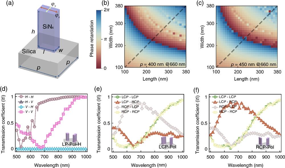
Fig. 2. Selection of the unit cell of metasurface polarizers. (a) Sketch of a dielectric meta-atom, which is sitting on a fused silica substrate. and indicate the phase retardation that the transmitted light carries in the and axes, respectively. Structure parameters, , , and , correspond to the height, length, and width of the meta-atom, respectively, and is the period of the square lattice. (b), (c) Phase retardation library at the wavelength of 660 nm. The height of the meta-atoms is kept at 1400 nm, and and are varied from 100 to 380 nm. The periods of the unit cell in panels (b) and (c) are 400 and 450 nm, respectively. (d)–(f) Simulation transmission coefficients of three kinds of metasurface polarizers, including horizontal linear polarizer (LP-Pol-H, , , , , and ), left circular polarizer (LCP-Pol, , , , , and ), and right circular polarizer (RCP-Pol, , , , , and ). For (d) LP-Pol-H, four combinations of polarization measurement schemes (horizontal polarization H and vertical polarization V) are calculated. H–H means that both the incident light and transmitted light are linearly polarized. Panels (e) and (f) show optical properties of the LCP-Pol and RCP-Pol. LCP and RCP: left- and right-circular polarizations.
Fig. 3. Experimental retrieval of the Jones matrix of the linear metasurface polarizer. The PSs of the incident light include linear polarizations along , , 45 deg, 135 deg directions, and left- and right-circular polarizations (LCP and RCP). After passing through the LP-Pol-H metasurface, the polarization ellipses directions of the transmitted light at wavelengths of 690 and 760 nm were measured. The dot and solid lines correspond to the measured and calculated data, respectively. From the calculated results, we can obtain the spin directions of the electric fields, which are indicated by the arrows. Each element of the Jones matrix is shown by the bar charts, in which the height and color are associated with the amplitude and phase.
Fig. 4. Polarization image encryption with the linear metasurface polarizers. (a) A schematic drawing of a tilted linear metasurface polarizer, which is rotated by an angle . (b) The layout of the linear metasurface polarizers. For letters M, E, T, and A, the corresponding rotation angles are , and 90 deg, respectively. The red pattern represents the incident Gaussian beam. (c), (d) The scanning electron microscope (SEM) images of the metasurfaces. The scale bars of the SEM images are (c) 20 and (d) , respectively. (e), (g) For incident light with LCP state, the intensity distribution of the four letters is measured at the wavelengths of 690 and 760 nm using a horizontal linear analyzer. (f), (h) The calculated intensity distribution of the four letters is based on the measured Jones matrix. The results in (e)–(h) are normalized to the maximum intensity values.
Fig. 5. Optical holography with circular metasurface polarizers. (a), (b) Schematics of the Fourier space holography based on RCP-Pol and LCP-Pol. The working wavelength is 700 nm. For the incident light with arbitrary PS, the circularly polarized output light carries a phase factor of , where is the rotation angle of the metasurface polarizer. (c), (k) The target intensity distribution of the holographic images. (d), (i) The calculated phase distributions of metasurface holograms. (e), (m) The reconstructed holographic images using the conditions in the experiment. (f), (n) The SEM images of RCP-Pol and LCP-Pol hologram devices (scale bar: 500 nm). The holographic images of (g)–(j) RCP-Pol and (o)–(r) LCP-Pol hologram devices were obtained under the measurements of four polarizer and analyzer (LCP and RCP) combinations.