
Yunfei LEI, Jinyuan LIU, Houzhi CAI, Junkun HUANG, Yong WANG, Pokun DENG. Characteristic Analysis of Chromatic Aberration of Pulse-dilation Framing Tube[J]. Acta Photonica Sinica, 2021, 50(8): 0850215
- Acta Photonica Sinica
- Vol. 50, Issue 8, 0850215 (2021)
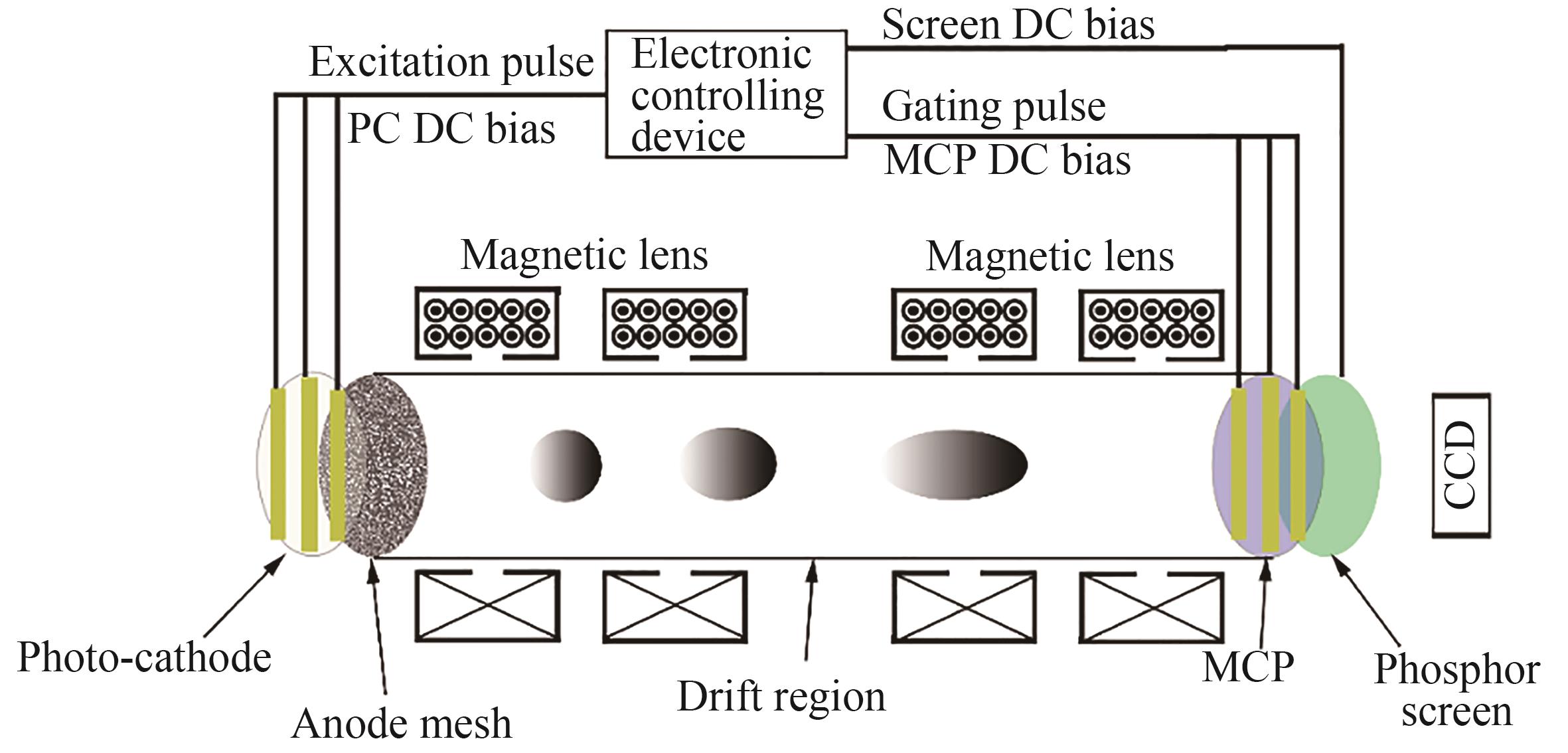
Fig. 1. Schematic diagram of the pulse-dilation framing tube
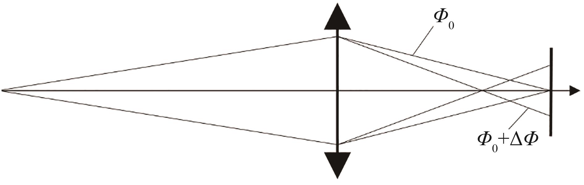
Fig. 2. Principle of the chromatic aberration
Fig. 3. Simulation model of the pulse-dilation framing tube
Fig. 4. Transient electrons scatter on the image plane with -3 000 V accelerating voltage on cathode at 0 time
Fig. 5. Spatial resolution versus times with -3 000 V accelerating voltage on cathode
Fig. 6. Duration 10 ps electrons scatter on the image plane with -3 000 V accelerating voltage on cathode at 0 time
Fig. 7. Spatial resolution versus times with -3 050 V accelerating voltage on cathode
Fig. 8. Photograph of the pulse-dilation framing tube
Fig. 9. Schematic diagram of the resolution mask on the PC
Fig. 10. Imaging result with different accelerating voltage on cathode
Fig. 11. Modulation of the mask versus the accelerating voltage on cathode
Fig. 12. Simulated result of the 15 lp/mm mask modulation versus the accelerating voltage on cathode

Set citation alerts for the article
Please enter your email address
© Copyright 2018-2021 | Chinese Laser Press. All Rights Reserved 沪ICP备15018463号-20