• Photonics Research
  • Vol. 9, Issue 6, 1084 (2021)
Shijie Feng1、2、3、*, Chao Zuo1、2、4、*, Liang Zhang1、2, Wei Yin1、2, and Qian Chen2、5、*
Author Affiliations
  • 1Smart Computational Imaging (SCI) Laboratory, Nanjing University of Science and Technology, Nanjing 210094, China
  • 2Jiangsu Key Laboratory of Spectral Imaging & Intelligent Sense, Nanjing University of Science and Technology, Nanjing 210094, China
  • 3e-mail: shijiefeng@njust.edu.cn
  • 4e-mail: zuochao@njust.edu.cn
  • 5e-mail: chenqian@njust.edu.cn
  • show less
    DOI: 10.1364/PRJ.420944 Cite this Article Set citation alerts
    Shijie Feng, Chao Zuo, Liang Zhang, Wei Yin, Qian Chen. Generalized framework for non-sinusoidal fringe analysis using deep learning[J]. Photonics Research, 2021, 9(6): 1084 Copy Citation Text show less
    Simulated sinusoidal fringe images and their cross sections. (a) An ideal sinusoidal pattern. (b) A gamma-distorted sinusoidal pattern. (c) A defocused binary stripe image. (d) A saturated sinusoidal fringe image. (e) A fringe image affected by both the gamma distortion and the image saturation. (f) A fringe image affected by both the defocusing and the image saturation.
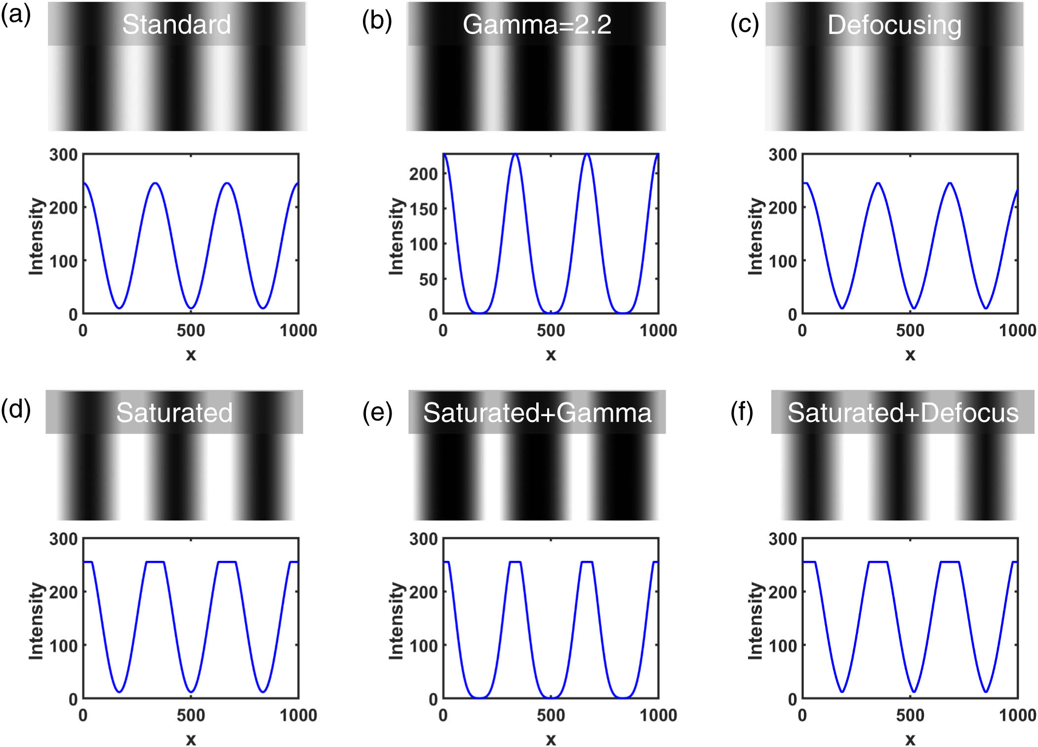
    Fig. 1. Simulated sinusoidal fringe images and their cross sections. (a) An ideal sinusoidal pattern. (b) A gamma-distorted sinusoidal pattern. (c) A defocused binary stripe image. (d) A saturated sinusoidal fringe image. (e) A fringe image affected by both the gamma distortion and the image saturation. (f) A fringe image affected by both the defocusing and the image saturation.
    Intensity and spectrum of different sinusoidal patterns. (a)–(c) The intensity profile of the ideal sinusoidal fringe, the gamma-distorted fringe, and the defocused fringe, respectively. (d)–(f) The corresponding spectra of (a)–(c).
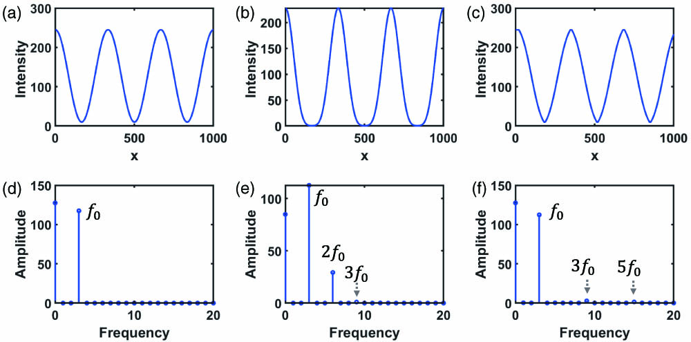
    Fig. 2. Intensity and spectrum of different sinusoidal patterns. (a)–(c) The intensity profile of the ideal sinusoidal fringe, the gamma-distorted fringe, and the defocused fringe, respectively. (d)–(f) The corresponding spectra of (a)–(c).
    Intensity and spectrum of different sinusoidal patterns. (a)–(c) The intensity profile of the saturated sinusoidal fringe, the saturated gamma-distorted fringe, and the saturated defocused fringe, respectively. (d)–(f) The corresponding spectra of (a)–(c).
    Fig. 3. Intensity and spectrum of different sinusoidal patterns. (a)–(c) The intensity profile of the saturated sinusoidal fringe, the saturated gamma-distorted fringe, and the saturated defocused fringe, respectively. (d)–(f) The corresponding spectra of (a)–(c).
    Performance of N-step phase-shifting algorithms for various kinds of non-sinusoidal fringes.
    Fig. 4. Performance of N-step phase-shifting algorithms for various kinds of non-sinusoidal fringes.
    Proposed deep neural network to process non-sinusoidal fringe images.
    Fig. 5. Proposed deep neural network to process non-sinusoidal fringe images.
    3D reconstructions from fringe images that were distorted by the projector’s gamma of 2.2. (a) One of the captured three-step PS images. (b) The 3D result obtained by the traditional three-step PS algorithm. (c) The 3D result obtained by the proposed method. (d) The 3D result obtained by the 12-step PS algorithm.
    Fig. 6. 3D reconstructions from fringe images that were distorted by the projector’s gamma of 2.2. (a) One of the captured three-step PS images. (b) The 3D result obtained by the traditional three-step PS algorithm. (c) The 3D result obtained by the proposed method. (d) The 3D result obtained by the 12-step PS algorithm.
    3D reconstructions of a pair of ceramic spheres when the projector’s gamma was 2.2. (a) One of the captured three-step PS images. (b) The 3D result obtained by the traditional three-step PS algorithm. (c) The 3D result obtained by the proposed method. (d) The 3D result obtained by the 12-step PS algorithm. (e) The absolute error map of the three-step PS algorithm. (f) The absolute error map of the proposed method.
    Fig. 7. 3D reconstructions of a pair of ceramic spheres when the projector’s gamma was 2.2. (a) One of the captured three-step PS images. (b) The 3D result obtained by the traditional three-step PS algorithm. (c) The 3D result obtained by the proposed method. (d) The 3D result obtained by the 12-step PS algorithm. (e) The absolute error map of the three-step PS algorithm. (f) The absolute error map of the proposed method.
    3D reconstructions of a ceramic plate when the gamma was 2.2. (a) The 3D result obtained by the traditional three-step PS algorithm (3PS). (b) The 3D result obtained by the deep-learning-based method (DL). (c) The 3D result obtained by the 12-step PS algorithm. (d) Comparison of the measurement errors of the three-step PS method and the proposed method.
    Fig. 8. 3D reconstructions of a ceramic plate when the gamma was 2.2. (a) The 3D result obtained by the traditional three-step PS algorithm (3PS). (b) The 3D result obtained by the deep-learning-based method (DL). (c) The 3D result obtained by the 12-step PS algorithm. (d) Comparison of the measurement errors of the three-step PS method and the proposed method.
    3D reconstructions with slightly defocused binary fringe images. (a) One of the three-step PS images. (b) The 3D result obtained by the traditional three-step PS algorithm. (c) The 3D result obtained by the proposed method. (d) The 3D result obtained by the 12-step PS algorithm.
    Fig. 9. 3D reconstructions with slightly defocused binary fringe images. (a) One of the three-step PS images. (b) The 3D result obtained by the traditional three-step PS algorithm. (c) The 3D result obtained by the proposed method. (d) The 3D result obtained by the 12-step PS algorithm.
    3D reconstructions of a pair of ceramic spheres with slightly defocused binary fringe images. (a) One of the captured three-step PS images. (b) The 3D result obtained by the traditional three-step PS algorithm. (c) The 3D result obtained by the proposed method. (d) The 3D result obtained by the 12-step PS algorithm. (e) The absolute error map of the three-step PS algorithm. (f) The absolute error map of the proposed method.
    Fig. 10. 3D reconstructions of a pair of ceramic spheres with slightly defocused binary fringe images. (a) One of the captured three-step PS images. (b) The 3D result obtained by the traditional three-step PS algorithm. (c) The 3D result obtained by the proposed method. (d) The 3D result obtained by the 12-step PS algorithm. (e) The absolute error map of the three-step PS algorithm. (f) The absolute error map of the proposed method.
    3D reconstructions of a ceramic plate with slightly defocused binary fringe images. (a) The 3D result obtained by the traditional three-step PS algorithm (3PS). (b) The 3D result obtained by the proposed method (DL). (c) The 3D result obtained by the 12-step PS algorithm. (d) Comparison of the measurement errors of the three-step PS method and the proposed method.
    Fig. 11. 3D reconstructions of a ceramic plate with slightly defocused binary fringe images. (a) The 3D result obtained by the traditional three-step PS algorithm (3PS). (b) The 3D result obtained by the proposed method (DL). (c) The 3D result obtained by the 12-step PS algorithm. (d) Comparison of the measurement errors of the three-step PS method and the proposed method.
    3D reconstructions with saturated PS images. (a) One of the captured three-step PS images. (b) The 3D result obtained by the traditional three-step PS algorithm. (c) The 3D result obtained by the proposed method. (d) The 3D result obtained by the 12-step PS algorithm.
    Fig. 12. 3D reconstructions with saturated PS images. (a) One of the captured three-step PS images. (b) The 3D result obtained by the traditional three-step PS algorithm. (c) The 3D result obtained by the proposed method. (d) The 3D result obtained by the 12-step PS algorithm.
    3D reconstructions of a pair of ceramic spheres with saturated fringe images. (a) One of the captured three-step PS images. (b) The 3D result obtained by the traditional three-step PS algorithm. (c) The 3D result obtained by the proposed method. (d) The 3D result obtained by the 12-step PS algorithm. (e) The absolute error map of the three-step PS algorithm. (f) The absolute error map of the proposed method.
    Fig. 13. 3D reconstructions of a pair of ceramic spheres with saturated fringe images. (a) One of the captured three-step PS images. (b) The 3D result obtained by the traditional three-step PS algorithm. (c) The 3D result obtained by the proposed method. (d) The 3D result obtained by the 12-step PS algorithm. (e) The absolute error map of the three-step PS algorithm. (f) The absolute error map of the proposed method.
    3D reconstructions of a ceramic plate with saturated fringe images. (a) The 3D result obtained by the traditional three-step PS algorithm (3PS). (b) The 3D result obtained by the proposed method (DL). (c) The 3D result obtained by the 12-step PS algorithm. (d) Comparison of the measurement errors of the three-step PS method and the proposed method.
    Fig. 14. 3D reconstructions of a ceramic plate with saturated fringe images. (a) The 3D result obtained by the traditional three-step PS algorithm (3PS). (b) The 3D result obtained by the proposed method (DL). (c) The 3D result obtained by the 12-step PS algorithm. (d) Comparison of the measurement errors of the three-step PS method and the proposed method.
    3D reconstructions under the coupling non-sinusoidal case where the gamma effect of 2.2 was coupled with the image saturation. (a) One of the captured three-step phase-shifting images. (b) The 3D result obtained by the traditional three-step PS algorithm. (c) The 3D result obtained by the proposed method. (d) The 3D result obtained by the 12-step PS algorithm.
    Fig. 15. 3D reconstructions under the coupling non-sinusoidal case where the gamma effect of 2.2 was coupled with the image saturation. (a) One of the captured three-step phase-shifting images. (b) The 3D result obtained by the traditional three-step PS algorithm. (c) The 3D result obtained by the proposed method. (d) The 3D result obtained by the 12-step PS algorithm.
    3D reconstructions of a pair of ceramic spheres in the coupling non-sinusoidal case where the gamma effect of 2.2 was coupled with the image saturation. (a) One of the captured three-step PS images. (b) The 3D result obtained by the traditional three-step PS algorithm. (c) The 3D result obtained by the proposed method. (d) The 3D result obtained by the 12-step PS algorithm. (e) The absolute error map of the three-step PS algorithm. (f) The absolute error map of the proposed method.
    Fig. 16. 3D reconstructions of a pair of ceramic spheres in the coupling non-sinusoidal case where the gamma effect of 2.2 was coupled with the image saturation. (a) One of the captured three-step PS images. (b) The 3D result obtained by the traditional three-step PS algorithm. (c) The 3D result obtained by the proposed method. (d) The 3D result obtained by the 12-step PS algorithm. (e) The absolute error map of the three-step PS algorithm. (f) The absolute error map of the proposed method.
    3D reconstructions of a ceramic plate in the coupling non-sinusoidal case where the gamma effect of 2.2 was coupled with the image saturation. (a) The 3D result obtained by the traditional three-step PS algorithm (3PS). (b) The 3D result obtained by the proposed method (DL). (c) The 3D result obtained by the 12-step PS algorithm. (d) Comparison of the measurement errors of the three-step PS method and the proposed method.
    Fig. 17. 3D reconstructions of a ceramic plate in the coupling non-sinusoidal case where the gamma effect of 2.2 was coupled with the image saturation. (a) The 3D result obtained by the traditional three-step PS algorithm (3PS). (b) The 3D result obtained by the proposed method (DL). (c) The 3D result obtained by the 12-step PS algorithm. (d) Comparison of the measurement errors of the three-step PS method and the proposed method.
    3D reconstructions under the coupling non-sinusoidal case where the images were projected through a slightly defocused projector and were captured with the pixel saturation. (a) One of the captured three-step phase-shifting images. (b) The 3D result obtained by the traditional three-step PS algorithm. (c) The 3D result obtained by the proposed method. (d) The 3D result obtained by the 12-step PS algorithm.
    Fig. 18. 3D reconstructions under the coupling non-sinusoidal case where the images were projected through a slightly defocused projector and were captured with the pixel saturation. (a) One of the captured three-step phase-shifting images. (b) The 3D result obtained by the traditional three-step PS algorithm. (c) The 3D result obtained by the proposed method. (d) The 3D result obtained by the 12-step PS algorithm.
    3D reconstructions of a pair of ceramic spheres under the coupling non-sinusoidal case where the effect of the slightly defocusing projection was coupled with the image saturation. (a) One of the captured three-step PS images. (b) The 3D result obtained by the traditional three-step PS algorithm. (c) The 3D result obtained by the proposed method. (d) The 3D result obtained by the 12-step PS algorithm. (e) The absolute error map of the three-step PS algorithm. (f) The absolute error map of the proposed method.
    Fig. 19. 3D reconstructions of a pair of ceramic spheres under the coupling non-sinusoidal case where the effect of the slightly defocusing projection was coupled with the image saturation. (a) One of the captured three-step PS images. (b) The 3D result obtained by the traditional three-step PS algorithm. (c) The 3D result obtained by the proposed method. (d) The 3D result obtained by the 12-step PS algorithm. (e) The absolute error map of the three-step PS algorithm. (f) The absolute error map of the proposed method.
    3D reconstructions of a ceramic plate under the coupling non-sinusoidal case where the effect of the slightly defocusing projection was coupled with the image saturation. (a) The 3D result obtained by the traditional three-step PS algorithm (3PS). (b) The 3D result obtained by the proposed method (DL). (c) The 3D result obtained by the 12-step PS algorithm. (d) Comparison of the measurement errors of the three-step PS method and the proposed method.
    Fig. 20. 3D reconstructions of a ceramic plate under the coupling non-sinusoidal case where the effect of the slightly defocusing projection was coupled with the image saturation. (a) The 3D result obtained by the traditional three-step PS algorithm (3PS). (b) The 3D result obtained by the proposed method (DL). (c) The 3D result obtained by the 12-step PS algorithm. (d) Comparison of the measurement errors of the three-step PS method and the proposed method.
    Shijie Feng, Chao Zuo, Liang Zhang, Wei Yin, Qian Chen. Generalized framework for non-sinusoidal fringe analysis using deep learning[J]. Photonics Research, 2021, 9(6): 1084
    Download Citation