
Weiwei Pang, Xiaobing Zheng, Jianjun Li, Xueshun Shi, Haoyu Wu, Maopeng Xia, Dongyang Gao, Jianmin Shi, Tao Qi, Qing Kang. Novel calibration optical path of cryogenic radiometer[J]. Chinese Optics Letters, 2015, 13(5): 051201
- Chinese Optics Letters
- Vol. 13, Issue 5, 051201 (2015)
Abstract
The application of cryogenic radiometer is a breakthrough in the measuring region of optical radiation with high precision. The measurement of laser power by means of cryogenic radiometer reaches a very high precision due to the fact that it combines electrical substitution, low temperature, and superconductivity technology. The significant achievement especially lies in the uncertainty of 0.005%–0.02% for the measurement of visible bands[
![]()
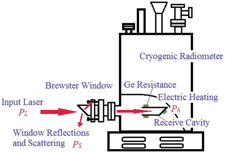
Figure 1.Laser power measurement based on cryogenic radiometer.
Limited to the influence from the structure and operation condition, generally speaking, cryogenic radiometer is used as the primary standard of radiation in the laboratory[
Figure
Sign up for Chinese Optics Letters TOC. Get the latest issue of Chinese Optics Letters delivered right to you!Sign up now
![]()
Figure 2.Transfer detector on calibration of cryogenic radiometer.
The calibration result for the transfer detector consists of detector responsivity and the corresponding uncertainty of calibration process. The latter is mainly caused by the uncertainty of the measurement of laser power
| Wavelength (nm) | |||||||
|---|---|---|---|---|---|---|---|
| Sources | 488 | 514 | 633 | 676 | 786 | 830 | 944 |
| Electrical power | 0.31 | 0.362 | 0.389 | 0.296 | 0.260 | 0.174 | 0.140 |
| Window transmittance | 1.525 | 0.609 | 1.529 | 0.437 | 0.453 | 0.521 | 0.520 |
| Receiver absorptance | 0.1 | ||||||
| Heating nonequivalence | 0.087 | ||||||
| Total uncertainty | 1.541 | 0.652 | 1.548 | 0.488 | 0.539 | 0.565 | 0.555 |
| Percent | 98.96 | 93.40 | 98.77 | 89.55 | 84.04 | 92.21 | 93.69 |
Table 1. Uncertainty on Measuring the Laser Power of Cryogenic Radiometera
It can be known from Table
We put forward a novel calibration structure based on the cryogenic radiometer, as shown in Fig.
![]()
Figure 3.Novel structure on the calibration of cryogenic radiometer.
This novel calibration system showed in Fig.
The cryogenic radiometer system, which serves the core of the whole calibration structure, was applied to measure the power of the incident laser with the accuracy being better than
| Technical Specifications | |
|---|---|
| Instrument model | Cryorad II |
| Spectrum | 0.25–50 μm |
| Receiver response | |
| Dynamic range | Max to 0.25 mW |
| Absolute accuracy | |
| Receiver absorptance | |
| Refrigeration mode | Liquid nitrogen |
| Liquid helium | |
| Calibration structure | Y-type |
| Demount Brewster window | No |
Table 2. Technique Parameter of Cryogenic Radiometer at the Anhui Institute of Optics and Fine Mechanics
In our calibration process, the optical schema was designed in Y-type configuration. In the incident direction, evacuating valve, vacuum gauge, bellows, vacuum pipe, triangle valve, and vacuum gate valve were assembled. The evacuating valve linked the vacuum units. The vacuum of the calibration system was monitored by the vacuum gauge. Under the premise of guarantying the vacuum pumping speed, KF25 connectors were adopted for universality.
To cushion the vibration of the triangle valve, a bellows was installed which was helpful to maintain the vacuum condition. The internal and external diameters of the bellows were 80 and 108 mm. The Brewster window was placed in front of the vacuum pipe.
The diameter of the detector cavity was 500 mm and the height was 400 mm. At the bottom of the detector cavity, a CF50 flange was installed which was used to switch to the main optical path. Besides the CF50 flange, a KF25 valve and a 55 core socket were set to exhaust. There was a transparent observation window that was intercalated to monitor the inside state.
The inner translation was sealed by magnetic fluid sealing techniques to meet the need of our calibration. The migration of the inner translation was more than 150 mm. The transfer detector to be calibrated was assembled on the guide rail, which was motivated by a magnetic fluid motor to switch into the optical path (Fig.
![]()
Figure 4.Transfer detector installed in detector cavity.
The cryogenic radiometer and the detector cavity were fixed on the motion control unit, and then the two pieces of equipment could be switched into the optical path alternately. The cryogenic radiometer could be ascended or descended therefore to make sure the equipment features accurate position alignment. Three lock carriers were installed inside the detector bin on the guide rail to accomplish the switch.
Vacuum units were for imparting a vacuum to the system and providing high-vacuum environment for the cryogenic radiometer. Vacuum units consisted of dry vacuum pump and molecular pump. The rate of dry vacuum pump reached to 4 and 200 L/S for the molecular pump. A vacuum monitor system was configured to monitor the calibration units with the range reached
The gate valve in the cryogenic radiometer branch was locked when the whole system was put under vacuum. First, we used dry vacuum pump to impart a vacuum to the Y-type optical path and the detector cavity before the molecular pump continued the vacuum mission. The connector between the bellows and detector cavity was KF25.
With respect to the cryogenic radiometer, a special vacuum unit was applied to achieve the vacuum degree needed. When the vacuum degree in both cryogenic radiometer and detector cavity reached
In the novel calibration structure, the entrance pupil of the cryogenic radiometer and the transfer detector could be switched to the same position of the concentric arcs alternately and then achieved the laser power of calibration beam entering into the cryogenic radiometer and transfer detector sharing the same characteristics. Meanwhile, in the front end of the transfer detector, an aperture cylinder whose inner diameter was 6 mm was installed. The inner diameter of the aperture was same to the reception cavity of the cryogenic radiometer so that the influence of stray light on both the pieces of equipment was also identical. At last, the laser power into the cryogenic radiometer and the transfer detector could be shown as
Therefore, it is only required to measure nonequivalence factor
In this novel calibration schema, we used a laser as the source to calibrate the standard transfer detector. The schema is shown as Fig.
![]()
Figure 5.Optical path on the calibration of cryogenic radiometer.
To verify the calibration accuracy of our new calibration schema, a comparison was made between this novel and traditional results. The details are listed in Table
| Absolute Spectral Responsivity (A/W) | ||
|---|---|---|
| Detector | Traditional | Novel (2014) |
| Trap-B | 0.5069 | 0.5045 |
| K | 0.4% | |
Table 3. Comparison on Responsivity of Transfer Detector in Novel Calibration Structure and Traditional Calibration Structure
From Eq. (
The uncertainty caused by the stray light, temperature drift, and data collection error is included in
| Source | Traditional Calibration | Novel Calibration Optical Path |
|---|---|---|
| Electrical power | 0.389 | 0.671 |
| Window transmittance | 1.529 | — |
| Receiver absorptance | 0.1 | 0.1 |
| Heating nonequivalence | 0.087 | 0.05195 |
| Laser power total uncertainty | 1.5832 | 0.6804 |
| Linearity | 0.434 | |
| Spatial uniformity | 1.99 | |
| Polarization sensitivity | 0.492 | |
| Stability | 0.687 | |
| Output V | 0.025 | 0.0244 |
| Total uncertainty ( | 2.715 | 2.321 |
Table 4. Compare of Combine Uncertainty of Transfer Detector between Traditional and Novela
It is proved from Table
In conclusion, we design and accomplish the optimization and upgrading on the calibration structure of cryogenic radiometer in China. We also make comparative analysis on the absolute spectral responsivity of the same transfer detector obtained from the calibration based on two different structures. The result shows that the consistence of the two calibration processes for the absolute spectral responsivity of the transfer detector is 0.4%. After the construction reform, the uncertainty decreases by 15% compared with that of the former construction. The experiment result shows that the novel calibration structure of cryogenic radiometer can reduce the uncertainty on traceability standard of radiometric calibration, avoid the dismounting of Brewster window after the calibration, improve the calibration accuracy, and eliminate the uncertainty caused by dismounting the window; therefore, it has a great significance on the calibration of transfer detector. This requires a transfer detector under tested are calibrated in a vacuum state, with vacuum compatibility requirements. If transfer detector is needed to work in the conditions of liquid nitrogen or helium refrigeration, the calibration method will no longer be suitable.
References
[1] J. E. Martin, N. P. Fox, P. G. Key. Metrologia, 21, 147(1985).
[2] P. V. Foukal, H. Kochling, P. Miller. Appl. Opt., 29, 988(1990).
[3] T. R. Gentile, J. M. Houston, J. E. Hardis. Appl. Opt., 35, 1056(1996).
[6] G. P. Eppeldauer, H. W. Yoon, J. Zeng, T. C. Larason. Metrologia, 49, 112(2012).
[7] A. Fehlmannl, G. Kopp, W. Schmutz, R. Winkler. Metrologia, 49, 34(2012).
[8] S. Cui, Z. Wang, S. Yang. Chin. Opt. Lett., 12, 110101(2014).
[9] J. Zhang, Y. Lin, J. Shao, Q. Fan. Acta Metrologica Sin., 19, 194(1998).
[10] X. Zheng, H. Wu, J. Zhang, Y. Liu, W. Zhou, L. Wang, Y. Qiao. Chin. Sci. Bull., 45, 1341(2000).
[11] M. Xia, J. Li, Z. Li, D. Gao, W. Pang, D. Li, X. Zheng. Chin. Opt. Lett., 12, 121201(2014).
[12] J. Li, X. Shi, X. Zheng, K. Chen, H. Wang, W. Zhang, P. Xie. Scientia Sin. Phys, Mech. Astron., 41, 749(2011).
[13] S. Li. The Continuous Spectral Radiometric Calibration at a Wide Spectrum Based on Cryogenic Radiometer(2006).
[14] X. Zheng, H. Wu, J. Zhang, W. Zhou, Y. Liu, L. Wang, Y. Qiao. Acta Opt. Sin., 21, 749(2001).
[15] J. Li, X. Zheng, Y. Lu, W. Zhang, P. Xie, P. Zou. Chin. Phys. Soc., 58, 6273(2009).
[16] Z. Yang, W. Fang, Y. Luo, Z. Xia. Chin. Opt. Lett., 12, 101202(2014).
[17] B. N. Taylor, C. E. Kuyatt. Guidelines for Evaluating and Expressing the Uncertainty of NIST Measurement Results.

Set citation alerts for the article
Please enter your email address
© Copyright 2018-2021 | Chinese Laser Press. All Rights Reserved 沪ICP备15018463号-20