
Jian Feng, Cunzhu Tong, Yufei Zhao, Andreas Popp, Berthold Schmidt, Lijie Wang, Bo Meng, Huanyu Lu, Yanjing Wang, Xin Zhang, Lijun Wang. Wavelength-tunable multi-point pump semiconductor disk laser based on an intra-cavity transmission grating[J]. Chinese Optics Letters, 2023, 21(2): 021401
- Chinese Optics Letters
- Vol. 21, Issue 2, 021401 (2023)
Abstract
1. Introduction
Semiconductor disk lasers (SDLs), also known as optically pumped vertical external cavity surface-emitting lasers (VECSELs), are very attractive for high power and high beam quality operation due to incorporating many attractive features of both semiconductor lasers and solid-state lasers[1–4]. Although the excellent heat dissipation performance is one of the main advantages of the disk form laser, the thermal effect in the active region is still a key factor limiting the power scaling of the SDL[5,6]. Splitting a single pump source or using multiple sources to pump multiple different regions on a disk is also called multi-point pumping[7,8]. This pumping method can distribute the pump power from one concentrated point to multiple different points and hence improve the heat dissipation. This will effectively reduce the temperature at the gain region of the disk laser and improve the performance of the output laser[9]. At present, there are two main methods to realize multi-point pumping. One is to design the structure of the cavity so that the multi-channel off-axis beams in the cavity form a closed loop[10–13]. Another method is to combine several independent intra-cavity laser beams in series through optical coupling to realize laser output[14–17].
The concept of multi-point pumping based on an intra-cavity transmission grating is similar to the spectral beam combining technology of fiber lasers and edge-emitting laser diode arrays[18–21]. Through the transform lens in the cavity, we can transform the distance separation among the multiple pump points into an angular separation that satisfies the grating diffraction condition. The photons circulating through the transmission grating in the cavity can form laser resonance only if their wavelength satisfied the diffraction conditions of the grating. By using this method, it can realize power scaling and maintain the beam quality as that of a single-point pump SDL. To obtain good performance while the multi-point pump disperses the heat source, we need to design a special laser resonator so that the optical gain generated by each spatially separated pump region can effectively contribute to the lasing.
In this paper, we demonstrated a resonator configuration scheme for multi-point pumping of the SDL. By adding a transmission diffraction grating in the external cavity, the SDL enables the selection and tuning of output wavelengths, and multiple pump gain regions can share the same resonator and output one laser beam containing multiple wavelengths. The number of the pumping points can be expanded in one dimension. The heat flow can be dissipated effectively, and the total gain volume and laser output power are improved.
Sign up for Chinese Optics Letters TOC. Get the latest issue of Chinese Optics Letters delivered right to you!Sign up now
2. Experiment Design and Setup
The experimental setup is shown in Fig. 1. The SDL chip structures are grown by metal-organic vapor phase epitaxy (MOVPE) on a GaAs substrate in reverse order. The active region consists of ten 8 nm InGaAs quantum wells (QWs) emitting at 1050 nm, equally spaced by GaAsP barrier layers with optimized anti-nodes positions of the standing wave in the optical cavity (a resonant periodic gain placement) to ensure a low threshold and homogeneous gain. The distributed Bragg reflector (DBR) is formed by 20 pairs of the AlAs/GaAs layers, which has a reflectivity higher than 99.9% at 1050 nm. The gain chip was cut into pieces for bonding. To minimize the effect of waste heat generated by the pump laser, thermal management of the gain medium was achieved by bonding to a pre-metalized diamond heat spreader via solid–liquid-interdiffusion bonding[22]. After the packaging step, the semiconductor substrate is removed by selective wet etching. The sample was further mounted on a copper heat sink, which was cooled by a Peltier element. The temperature of the heat spreader was controlled at .
![]()
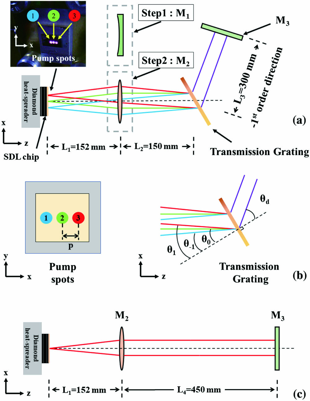
Figure 1.Schematic diagram of the experiment setup. (a) Multi-point pumped SDL with an intra-cavity transmission grating. (b) The geometric relationship of pump spots and transmission diffraction grating. (c) Linear straight cavity with the same cavity length as (a).
Figure 1(a) shows the schematic diagram of the multi-point pumped SDL. Three fiber-coupled pump lasers emitting at 808 nm are used as the multi-point pump source. They are imaged on the SDL chip surface at different points by focusing lens groups with a separation distance of in the -axis direction, and the focused spots with the same diameter of . The laser cavity was formed by the SDL chip’s DBR mirror and the output coupler. A transition grating T-1000-1040-3225-94 from FINISAR was employed as a diffractive spectroscopic element, which is located in the cavity. The polarization-independent transmission grating has 1000 lines/mm and provides a first-order diffraction efficiency of near 1040 nm wavelength at the angle. The optical grating performance will remain substantially similar over a 5° variation in the angle of incidence.
Because of the diffraction effect of the grating, the optical path of the resonant cavity will be deflected. It needs two steps to locate the grating into the cavity. Firstly, we use a plano-concave output coupling mirror with a curvature radius of 500 mm and transmittance of 3% to build a straight cavity under No. 2 single-point pumping. is 152 mm, and the grating is set at a distance behind in the direction of the laser output. Then, the accurate diffraction angle with the highest efficiency at the expected wavelength is determined by the angle of rotating the grating. The plane output coupling mirror with a transmittance of 3% is set in the st diffraction direction, with a distance . Adjust the deflection angle of so that the st-order diffracted light of the grating returns along the original optical path and forms a composite cavity with the previous output coupling cavity. Here, the direction and angle of the transmission grating and mirror strictly satisfy the grating equation of the target wavelength. In the second step, fix the position and angle of the transmission grating and , turn off the pump source, and replace mounted on the mirror mount with convex lens with the same outer diameter as . The focal length of is , equal to . Then, turn on the pump source and fine-tune and to form the resonance and maximize the output laser power.
For the intra-cavity transmission grating, the incident grating angle and the st diffraction angle satisfy the diffraction equation:
For multi-point pumping, the distance between pump points is , as shown in Fig. 1(b). The resonant wavelength of the central pump point No. 2 on the optical axis is , and the incident angle on the grating . Assume that the focused pump light is arranged linearly in one dimension, and the number of pump points is . The resonant wavelengths of the pump points on both sides of the center point are , and the angles of their incident gratings are , with being a fixed positive integer. For each pump point, the resonant wavelength and incident angle on the grating satisfy Eq. (1), and the diffractive angles are the same. According to the geometric relationship between the pump points, the angle of the incident grating of the th pump point is
The resonant wavelength interval between adjacent pump points is
When the focal length is large enough, the smaller the distance between adjacent pump points, the more the pump points can be accommodated in the same spectral range, and the greater the gain volume and output power. When the number of pump points is small and is much larger than , the wavelength interval and the wavelength of the th pump point can be further approximated as
Based on our experimental setup, the calculated wavelength interval between the three pump points should be . For the central pump spot No. 2, if we assume that is equal to half the diameter of the pump spot of , we can also use Eq. (5) to estimate the width of . The calculated spectral width is . This value is only determined by the grating diffraction equation unless the gain spectral width is smaller than this value.
To study the influence of the intra-cavity transmission grating on the output performance of the laser, a group of linear straight cavities is set up with the same cavity length but no grating as the free-running control, which is shown in Fig. 1(c), where , , and are the same as those in Fig. 1(a). The position of is with . The diameter of the mode size on the gain chip is so that the laser can operate in multi-mode with high output power.
3. Results and Discussion
To characterize the influence of the transmission grating on the output performance of the laser, two different laser cavities with the same cavity length were used. One is the linear straight cavity shown in Fig. 1(c), and the other one is the cavity with the transmission grating under the center-point No. 2 single-point pumping shown in Fig. 1(a). The laser wavelength was fixed to 1048 nm by tuning the angle of the grating and output coupler. Figure 2(a) plots the output power as a function of incident pump power. The output power of the laser with the transmission grating is about 10% lower than that of the linear straight cavity at the same pump power. Because the wavelength selective effect of the intra-cavity grating enables the laser to operate at a relatively longer wavelength, the lasing threshold is also increased accordingly. At 29.3 W pump power, the emitting wavelength was measured. Due to the diffraction effect of the intra-cavity transmission grating on the wavelength, the full width at half-maximum (FWHM) of the laser wavelength is compressed from 4.8 nm to 1.0 nm. This spectral width value is consistent with our calculated .
![]()
Figure 2.(a) Output power curve of the linear straight cavity and the cavity with transmission grating. Inset: spectrum measured at 29.3 W pump power. (b) Laser beam waist size of the two cavities at different pump power. (c) Output power curve of the two cavities in units of kW/cm2.
We also tested the beam quality factor and beam waist spot size of the output laser. The beam waist spot size of the two cavities at different pump power is shown in Fig. 2(b). In the linear straight cavity, the beam waist spot of the laser will increase uniformly with the increase of pump power and output power because the laser operates in multi-mode. The beam waist spot changes from an approximate circle to an ellipse with the insertion of the transmission grating into the cavity. The main reason for this change is the diffraction effect of the intra-cavity grating. Diffractive elements in a resonant cavity can alter the distribution of optical fields and perform the mode selection[23,24]. Diffractive elements in the cavity usually show a larger mode loss for high-order modes than that of the fundamental mode. Since the grating used in our experiments only has lines in the direction, the mode selective loss only exists in the direction. Therefore, the laser in the direction can only resonate in fewer modes, and the corresponding beam waist spot size is relatively small.
Here, if we use the power density to describe the output laser performance, we can get Fig. 2(c). The power density of the pump laser is the power divided by the pump spot size. The power density of the output laser is the output power divided by the beam waist spot size at different pump power. Due to the change in the beam waist size, the output power density of the cavity with the intra-cavity transmission grating is significantly higher than that of the linear straight cavity, or we can say that the laser brightness is improved.
Figure 3(a) shows the free-running emission spectrum at different output powers in the linear straight cavity. The emission spectrum broadens and redshifts with the increase of incident pump power, output power, and temperature. The range of the free-running spectrum that reflects the range of gain peaks varies with temperature, which is about 1043 nm to 1051 nm. The gain spectrum width of QWs will be slightly wider than this range. The grating and output coupling mirror were adjusted to different emitting wavelengths, and the maximum output power according to the tuning wavelength is shown in Fig. 3(b). A wavelength tuning range of , from 1036 nm to 1054 nm, could be covered. Longer wavelengths greater than 1054 nm can theoretically be achieved but require higher operating temperatures and higher thresholds. It is limited by the heat dissipation capacity of the SDL device.
![]()
Figure 3.(a) Emission spectrum at different output powers in the linear straight cavity. (b) Spectrum and maximum output power of the cavity with transmission grating measured at different wavelength tuning points.
For multi-point pumping, we adjusted the wavelength of the No. 2 output laser corresponding to the center pump point to 1048 nm, near the maximum gain wavelength of 1050 nm. The laser wavelengths are, respectively, 1045 nm and 1051 nm corresponding to pump points No. 1 and No. 3. Their spectrum was the same as the green, purple, and brown curves in Fig. 3(b), respectively. Due to the difference in pump area, the horizontal axis of Fig. 4 is uniformly set as the total incident pump power density, and the pump power of each point is equal. The sum of the output power values of their single-point pump separate operation is shown in Fig. 4 as a comparison. Its meaning as a comparison is the theoretically achievable output power value if multiple pump points are not affected by heating each other.
![]()
Figure 4.Output power curve of multi-point pump SDL with an intra-cavity transmission grating. (a) No. 1 and No. 3 two-point synchronous pumping. (b) No. 1, No. 2, and No. 3 three-point synchronous pumping.
Figure 4(a) shows the power curve of the output laser when driving the pump sources No. 1 and No. 3 together. The separation between the two pump points is . The power curve of the two-point synchronous pumping is relatively small and affected by the distance between the pump points, which is very close to the sum of the output power when the two points are pumped separately. The inset of Fig. 4(a) gives the measured spectrum of the laser at the output power density of . The spectrum of the emitting laser pumped by the two points contains the spectrum of No. 1 and No. 3 single-point pump output at the same time. The separation between the two peaks of the spectrum is about 6 nm, which is close to double our theoretical analysis value.
Figure 4(b) shows the power curve of the output laser with three pump sources driving together. The separation between No. 1, No. 2, and No. 3 pump points is . When the total pump power density is less than , the output laser power density is very close to the sum value, similar to Fig. 4(a). Above the pump power density of , the output power density decreases significantly. The output laser power density decreases after reaching a maximum of due to the thermal effect. Compared with Fig. 4(a), the main reason is the close distance between the three pump points causes the cross of heat flow. Moreover, the Peltier element temperature control system detects that the temperature of the backside of the SDL chip is out of control when the total pump power density is higher than . The inset of Fig. 4(b) gives the measured spectrum of the laser at maximum output power density. The separation between the three peaks of the spectrum is about 2.8 nm, which is also close to our theoretical analysis value. When the total heat flux approaches the upper limit of the heat dissipation capacity of the single heat sink, the power and spectrum of the output laser will deteriorate. Therefore, to obtain high output power, we can further improve heat dissipation by designing the separated heat sinks for each pumping point or using an in-well pump or electrical pump SDL with higher efficiency and less heat generation[25,26].
The beam quality of the SDL with different cavities and pump schemes was measured and is shown in Fig. 5. The beam quality factor of the linear straight cavity increases with pump power density because the laser operates in multi-mode, as shown in Fig. 5(a). The factor and near-field pattern were altered after insertion of the transmission grating into the cavity, as shown in Fig. 5(b). The beam quality factor is compressed to , while the is close to the maximum in the straight cavity. The change in the factor is the same as the previous explanation for the beam waist change in Fig. 2(a), which is caused by the diffraction effect of the intra-cavity grating. The higher loss of the diffractive element in the cavity for higher-order modes also results in the change of the factor. Since the grating only has lines in the direction, only the is significantly limited. The factor results of multi-point pumping shown in Fig. 5(c) are consistent with those in Fig. 5(b), which shows that the multi-point pumping scheme will not significantly change the beam quality compared with the single-point pumping. If a gain structure with multiple QWs and a wider gain spectrum is used[27,28], the multi-point pumping scheme can be further extended in the direction without affecting the factor by using commercial gratings. By designing the fine structure of the transmission grating, it is expected to produce mode loss for high-order modes in both the and directions.
![]()
Figure 5.Pump-power-dependent M2 factors for (a) the linear straight cavity, (b) No. 2 single-point pumping cavity with transmission grating, (c) No. 1, No. 2, and No. 3 three-point pumping cavity.
4. Conclusion
In summary, we have demonstrated a resonant cavity with an intra-cavity transmission grating and verified a wavelength-tunable multi-point pump SDL scheme on this basis. The effect of the intra-cavity grating on the output laser power, wavelength, and beam quality was investigated. It realized the tunable wavelength range . In the case of two-point pumping, the output power is affected relatively little by the distance between the pump points, which is very close to the sum of the output power when the two points are pumped separately. In the case of three-point pumping, the output power cannot be further improved, which is mainly affected by the close distance between the pump points, the cross of heat flow, and the upper limit of the heat dissipation capacity of the single heat sink. The changes in beam quality factor and near-field pattern are due to the mode selective loss by the intra-cavity grating. The multi-point pump scheme still has sufficient space to be scaled up to a higher level of output power, such as using SDL chips with wider gain spectral width to achieve more pump points and pump point spacing expansion and optimizing the thermal management to increase the total output power.
References
[1] B. Heinen, T. L. Wang, M. Sparenberg, A. Weber, B. Kunert, J. Hader, S. W. Koch, J. V. Moloney, M. Koch, W. Stolz. 106 W continuous-wave output power from vertical-external-cavity surface-emitting laser. Electron. Lett., 48, 516(2012).
[2] T. Leinonen, V. Iakovlev, A. Sirbu, E. Kapon, M. Guina. 33 W continuous output power semiconductor disk laser emitting at 1275 nm. Opt. Express, 25, 7008(2017).
[3] L. Fan, M. Fallahi, J. T. Murray, R. Bedford, Y. Kaneda, A. R. Zakharian, J. Hader, J. V. Moloney, W. Stolz, S. W. Koch. Tunable high-power high-brightness linearly polarized vertical-external-cavity surface-emitting lasers. Appl. Phys. Lett., 88, 021105(2006).
[4] B. W. Tilma, M. Mangold, C. A. Zaugg, S. M. Link, D. Waldburger, A. Klenner, A. S. Mayer, E. Gini, M. Golling, U. Keller. Recent advances in ultrafast semiconductor disk lasers. Light Sci. Appl., 4, e310(2015).
[5] A. Giesen, H. Hügel, A. Voss, K. Wittig, U. Brauch, H. Opower. Scalable concept for diode-pumped high-power solid-state lasers. Appl. Phys. B, 58, 365(1994).
[6] P. Zhang, T. Dai, Y. Wu, Y. Ni, Y. Zhou, L. Qin, Y. Liang, S. Fan. Substrate-removed semiconductor disk laser with 0.6 W output power. Chin. Opt. Lett., 10, S11401(2012).
[7] S. V. Garnov, V. A. Mikhailov, R. V. Serov, V. A. Smirnov, V. B. Tsvetkov, I. A. Shcherbakov. Study of the possibility of developing a multichannel-diode-pumped multikilowatt solid-state laser based on optically dense active media. Quantum Electron., 37, 910(2007).
[8] D. A. Guryev, D. A. Nikolaev, V. B. Tsvetkov. Nd:GGG disk laser with multipoint spatially periodic optical pumping. Laser Phys. Lett., 13, 045003(2016).
[9] D. A. Guryev, D. A. Nikolaev, V. B. Tsvetkov, I. A. Shcherbakov. Thermally induced optical deformation of a Nd:YVO4 active disk under the action of multi-beam spatially periodic diode pumping. Laser Phys. Lett., 15, 055003(2018).
[10] A. M. Bul’kanov, D. A. Nikolaev, V. B. Tsvetkov, A. I. Shamatova, I. A. Shcherbakov. Single-mode Nd:GGG disk laser with three-beam diode pumping and a degenerate cavity. Quantum Electron., 48, 468(2018).
[11] D. A. Nikolaev, V. B. Tsvetkov. CW TEM00 spectral narrow band Nd:YVO4 disk laser with two-mirror degenerate cavity configuration. Laser Phys., 31, 095002(2021).
[12] E. J. Saarinen, A. Härkönen, S. Suomalainen, O. G. Okhotnikov. Power scalable semiconductor disk laser using multiple gain cavity. Opt. Express, 14, 12868(2006).
[13] B. Rosener, M. Rattunde, R. Moser, C. Manz, K. Kohler, J. Wagner. GaSb-based optically pumped semiconductor disk laser using multiple gain elements. IEEE Photon. Technol. Lett., 21, 848(2009).
[14] D. A. Guryev, D. A. Nikolaev, V. B. Tsvetkov. Nd:YVO4 disk laser with multipoint diode pumping and diffraction limited output. Laser Phys. Lett., 16, 075002(2019).
[15] C. Hessenius, M. Lukowski, M. Fallahi. High-power tunable two-wavelength generation in a two chip co-linear T-cavity vertical external-cavity surface-emitting laser. Appl. Phys. Lett., 101, 121110(2012).
[16] S. De, G. Baili, M. Alouini, J.-C. Harmand, S. Bouchoule, F. Bretenaker. Class-A dual-frequency VECSEL at telecom wavelength. Opt. Lett., 39, 5586(2014).
[17] A. C. Sills, G. N. West, E. A. Fennig, M. P. Grimshaw, M. T. Johnson, M. Kanskar, K. D. Choquette, P. O. Leisher. In-phase coherently-coupled optically-pumped VECSEL array. IEEE Photon. Technol. Lett., 26, 430(2014).
[18] E. J. Bochove. Theory of spectral beam combining of fiber lasers. IEEE J. Quantum Electron., 38, 432(2002).
[19] V. Daneu, A. Sanchez, T. Y. Fan, H. K. Choi, G. W. Turner, C. C. Cook. Spectral beam combining of a broad-stripe diode laser array in an external cavity. Opt. Lett., 25, 405(2000).
[20] J. T. Gopinath, B. Chann, T. Y. Fan, A. Sanchez-Rubio. 1450-nm high-brightness wavelength-beam combined diode laser array. Opt. Express, 16, 9405(2008).
[21] J. Zhang, H. Peng, X. Fu, Y. Liu, L. Qin, G. Miao, L. Wang. CW 50 W/M2 = 10.9 diode laser source by spectral beam combining based on a transmission grating. Opt. Express, 21, 3627(2013).
[22] G. Y. Hou, S. L. Shu, J. Feng, A. Popp, L. J. Wang. High power (>27 W) semiconductor disk laser based on pre-metalized diamond heat-spreader. IEEE Photonics J., 11, 1501908(2019).
[23] G. Mowry, J. R. Leger. Large-area, single-transverse-mode semiconductor laser with diffraction-limited super-Gaussian output. Appl. Phys. Lett., 66, 1614(1995).
[24] J. R. Leger, G. Mowry, X. Li. Modal properties of an external diode-laser-array cavity with diffractive mode-selecting mirrors. Appl. Opt., 34, 4302(1995).
[25] S. Hövel, A. Bischoff, N. C. Gerhardt, M. R. Hofmann, T. Ackemann, A. Kroner, R. Michalzik. Optical spin manipulation of electrically pumped vertical-cavity surface-emitting lasers. Appl. Phys. Lett., 92, 041118(2008).
[26] S. S. Beyertt, M. Zorn, T. Kubler, H. Wenzel, M. Weyers, A. Giesen, G. Trankle, U. Brauch. Optical in-well pumping of a semiconductor disk laser with high optical efficiency. IEEE J. Quantum Electron., 41, 1439(2005).
[27] A. Broda, A. Wojcik-Jedlinska, I. Sankowska, M. Wasiak, M. Wieckowska, J. Muszalski. A 95-nm-wide tunable two-mode vertical external cavity surface-emitting laser. IEEE Photon. Technol. Lett., 29, 2215(2017).
[28] Z. Yang, A. R. Albrecht, J. G. Cederberg, M. Sheik-Bahae. Optically pumped DBR-free semiconductor disk lasers. Opt. Express, 23, 33164(2015).

Set citation alerts for the article
Please enter your email address
© Copyright 2018-2021 | Chinese Laser Press. All Rights Reserved 沪ICP备15018463号-20