• Chinese Journal of Lasers
  • Vol. 50, Issue 20, 2002102 (2023)
Baohua Zhu1,2, Sicheng Niu3, Qige Li3, Shuming Zhao2..., Xing Lu3, Caiwang Tan3,* and Xiaoguo Song3|Show fewer author(s)
Author Affiliations
  • 1School of Materials Science and Engineering, Harbin Institute of Technology at Shenzhen, Shenzhen 518055, Guangdong, China
  • 2Shenzhen JPT Opto-electronics Co., Ltd., Shenzhen 518110, Guangdong, China
  • 3State Key Laboratory of Advanced Welding and Joining, Harbin Institute of Technology, Harbin 150001, Heilongjiang, China
  • show less
    DOI: 10.3788/CJL230681 Cite this Article Set citation alerts
    Baohua Zhu, Sicheng Niu, Qige Li, Shuming Zhao, Xing Lu, Caiwang Tan, Xiaoguo Song. Microstructures and Properties of Nanosecond Laser Welded Cu/Al/Cu Joints Under Different Welding Speeds[J]. Chinese Journal of Lasers, 2023, 50(20): 2002102 Copy Citation Text show less
    Schematics of Cu/Al/Cu sheet structure welding . (a) Welding fixing device; (b) laser scanning path
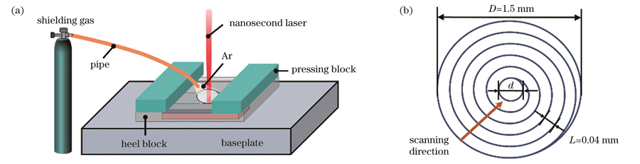
    Fig. 1. Schematics of Cu/Al/Cu sheet structure welding . (a) Welding fixing device; (b) laser scanning path
    Tensile shear diagrams of Cu/Al/Cu laminar sheet joint. (a) Lap diagram of joint; (b) schematic of shear force test
    Fig. 2. Tensile shear diagrams of Cu/Al/Cu laminar sheet joint. (a) Lap diagram of joint; (b) schematic of shear force test
    Surface morphologies of Cu/Al/Cu laminar sheet joints under different welding speeds. (a)-(e) Optical mirror morphologies; (b)-(j) optical 3D structures; (k)-(o) SEM morphologies
    Fig. 3. Surface morphologies of Cu/Al/Cu laminar sheet joints under different welding speeds. (a)-(e) Optical mirror morphologies; (b)-(j) optical 3D structures; (k)-(o) SEM morphologies
    Cross-section morphologies of Cu/Al/Cu laminar joints under different welding speeds. (a)(f) 15 mm·s-1; (b)(g) 18 mm·s-1; (c)(h) 21 mm·s-1; (d)(i) 24 mm·s-1; (e)(j) 27 mm·s-1
    Fig. 4. Cross-section morphologies of Cu/Al/Cu laminar joints under different welding speeds. (a)(f) 15 mm·s-1; (b)(g) 18 mm·s-1; (c)(h) 21 mm·s-1; (d)(i) 24 mm·s-1; (e)(j) 27 mm·s-1
    Weld geometry characteristics of Cu/Al/Cu laminar structures. (a) Schematic of weld structure; (b) weld reinforcement and penetration depth
    Fig. 5. Weld geometry characteristics of Cu/Al/Cu laminar structures. (a) Schematic of weld structure; (b) weld reinforcement and penetration depth
    Interfacial microstructures of typical Cu/Al/Cu laminar joints under different welding speeds. (a)-(c) 15 mm·s-1; (d)-(f) 21 mm·s-1; (g)-(i) 27 mm·s-1
    Fig. 6. Interfacial microstructures of typical Cu/Al/Cu laminar joints under different welding speeds. (a)-(c) 15 mm·s-1; (d)-(f) 21 mm·s-1; (g)-(i) 27 mm·s-1
    Line scanning results of positions marked by arrows in Fig.6 under different welding speeds. (a)(b) 15 mm·s-1; (c)(d) 21 mm·s-1; (e)(f) 27 mm·s-1
    Fig. 7. Line scanning results of positions marked by arrows in Fig.6 under different welding speeds. (a)(b) 15 mm·s-1; (c)(d) 21 mm·s-1; (e)(f) 27 mm·s-1
    Interfacial element distributions of Cu/Al/Cu laminar joints under different welding speeds. (a)-(d) 15 mm·s-1; (e)-(h) 21 mm·s-1; (i)-(l) 27 mm·s-1
    Fig. 8. Interfacial element distributions of Cu/Al/Cu laminar joints under different welding speeds. (a)-(d) 15 mm·s-1; (e)-(h) 21 mm·s-1; (i)-(l) 27 mm·s-1
    Shear force test results of Cu/Al/Cu laminar joints under different welding speeds
    Fig. 9. Shear force test results of Cu/Al/Cu laminar joints under different welding speeds
    Fracture surface morphologies of typical Cu/Al/Cu laminar sheet joints under different welding speeds. (a)-(c) Optical mirror morphologies; (d)-(f) 3D features for Al-side fractures; (g)-(i) 3D features for Cu-side fractures
    Fig. 10. Fracture surface morphologies of typical Cu/Al/Cu laminar sheet joints under different welding speeds. (a)-(c) Optical mirror morphologies; (d)-(f) 3D features for Al-side fractures; (g)-(i) 3D features for Cu-side fractures
    SEM fracture surface morphologies of typical Cu/Al/Cu laminar sheet joints under different welding speeds. (a)(d) 15 mm·s-1;(b)(e) 21 mm·s-1; (c)(f) 27 mm·s-1
    Fig. 11. SEM fracture surface morphologies of typical Cu/Al/Cu laminar sheet joints under different welding speeds. (a)(d) 15 mm·s-1;(b)(e) 21 mm·s-1; (c)(f) 27 mm·s-1
    Failure mechanism diagrams of Cu/Al/Cu nanosecond pulsed laser welded joints under different welding speeds. (a) 15 mm/s;(b) 21 mm/s; (c) 27 mm/s
    Fig. 12. Failure mechanism diagrams of Cu/Al/Cu nanosecond pulsed laser welded joints under different welding speeds. (a) 15 mm/s;(b) 21 mm/s; (c) 27 mm/s
    MaterialOCuMgAlZnCrSi
    6063Al-0.100.45-0.90Bal.0.01-0.20-0.60
    T2 Cu0.0600Bal.--0.00500.00080.0050
    Table 1. Chemical compositions of 6063 Al alloy and T2 Cu (mass fraction, %)
    Process parameterValue
    Pulse frequency /kHz70
    Laser power /W70
    Defocused distance /mm0
    Scanning speed /(mm·s-115,18,21,24,27
    Pulse width /ns240
    Shielding gas pressure /MPa0.6
    Table 2. Parameters for nanosecond pulsed laser welding of Cu/Al/Cu
    Point No.Atomic fraction /%Possible phase
    CuAl
    125.2074.48CuAl2
    273.7126.29Cu9Al4
    332.5867.42CuAl2
    433.5966.41CuAl2
    557.1042.90Cu4Al3
    624.9475.06CuAl2
    758.6841.32Cu4Al3
    822.2477.76CuAl2
    933.2566.75CuAl2
    Table 3. EDS results of marked points in Fig. 6
    Point No.Atomic fraction /%Possible phase
    CuAl
    132.4664.54CuAl2
    293.466.54Cu
    368.3931.61Cu9Al4
    44.7395.27Al
    599.340.66Cu
    631.5468.46CuAl2
    794.435.57Cu
    899.450.55Cu
    933.2466.76CuAl2
    Table 4. EDS results of marked regions in Fig. 11
    Baohua Zhu, Sicheng Niu, Qige Li, Shuming Zhao, Xing Lu, Caiwang Tan, Xiaoguo Song. Microstructures and Properties of Nanosecond Laser Welded Cu/Al/Cu Joints Under Different Welding Speeds[J]. Chinese Journal of Lasers, 2023, 50(20): 2002102
    Download Citation