
Jinzhao Wang, Ting Li, Yang Feng, Jiewen Li, Wanxin Li, Luwei Ding, Yong Yao, Jianan Duan, Wei Liu, Feng He, Yi Zou, Xiaochuan Xu, "On-chip ultra-high rejection and narrow bandwidth filter based on coherency-broken cascaded cladding-modulated gratings," Photonics Res. 12, 979 (2024)
- Photonics Research
- Vol. 12, Issue 5, 979 (2024)
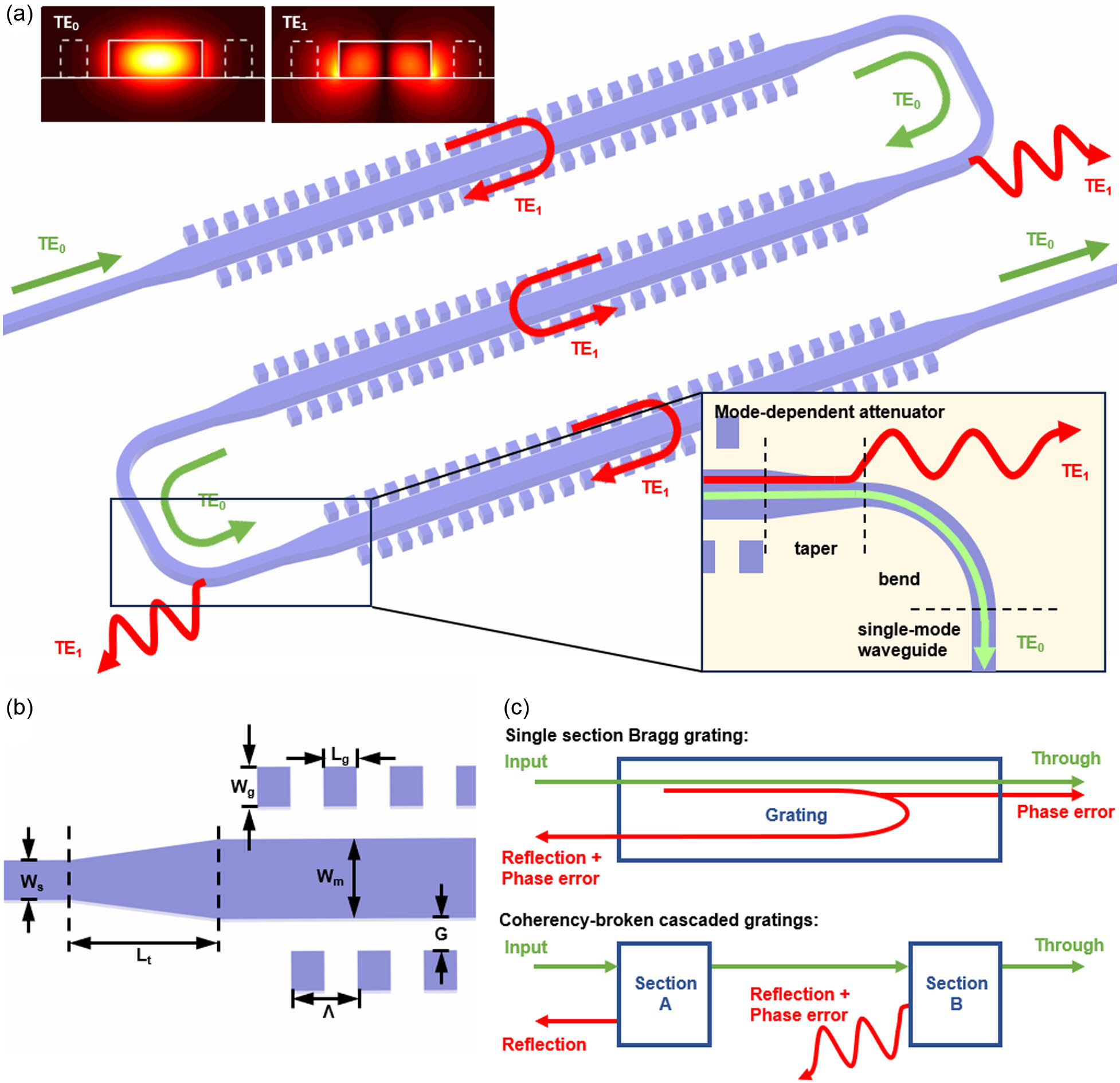
Fig. 1. (a) Schematic of the proposed coherency-broken cascaded cladding-modulated Bragg grating filter. The incident fundamental mode (TE 0 TE 1 TE 1 TE 0 TE 1 TE 0 TE 1 TE 1 TE 0
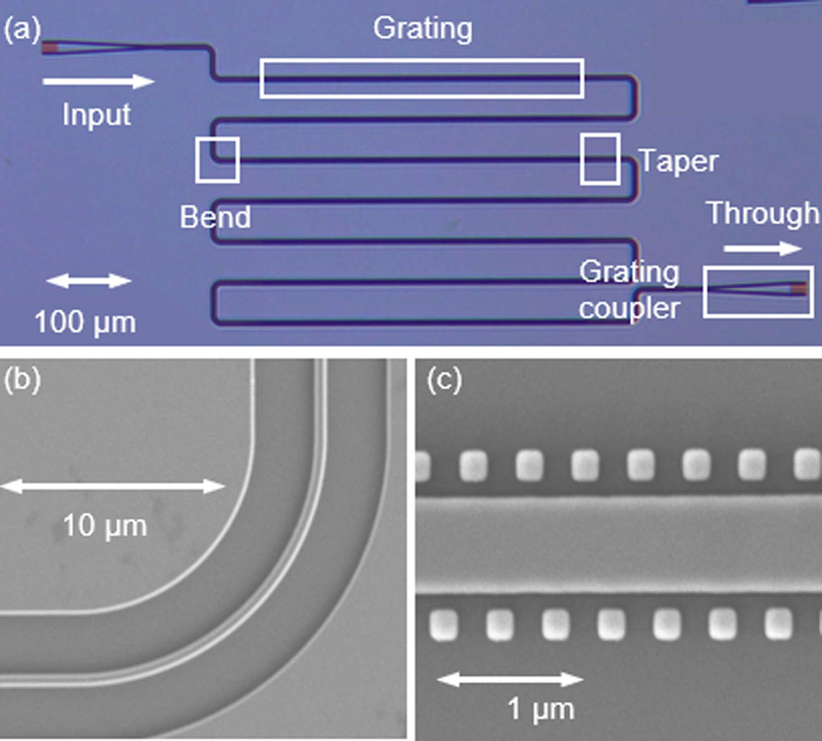
Fig. 2. (a) Microscope image of one of the fabricated coherency-broken cascaded grating filters comprising seven Bragg grating filters. Scanning electron microscope image of (b) single-mode waveguide bend and (c) cladding-modulated grating filter.
Fig. 3. Measured transmission spectra of single-section Bragg filter with (a) different gap widths ranging from 80 to 110 nm, and (b) single-section filters with different grating lengths ranging from 400 to 2000 μm while gap G
Fig. 4. Measured transmission spectra of (a) single-section 2000-μm-long Bragg filter without artificial imperfections, (b) single-section 2000-μm-long Bragg filters with artificial imperfections, and (c) two sections of cascaded 1000-μm-long Bragg filters with artificial imperfections. The insets of (b) show the grating structure in three different cases, where the introduced imperfections are denoted by red dots.
Fig. 5. (a) Measured transmission spectra of 2000 μm × 1 500 μm × 4 250 μm × 8 125 μm × 16 100 μm × 20
| |||||||||||||||||||||||||||||||||||||||||||
Table 1. Recent Results of On-Chip Silicon Filters Based on Bragg Gratings


Set citation alerts for the article
Please enter your email address

© Copyright 2018-2021 | Chinese Laser Press. All Rights Reserved 沪ICP备15018463号-20