Spectral polarization imaging technology is a novel optical imaging technique that not only enhances the amount of information acquired from targets, but also reduces background noise, which can capture target details and detect disguised targets. This paper presents a spectro-polarimetric device by integrating subwavelength gratings with Fabry-Perot (F-P) filter, which can obtain ultra-high spectral resolution and polarization extinction ratio with high control flexibly on both spectrum and polarization. A spectro-polarimetric filter (SPF) has been designed to obtain 4 spectral channels of stokes parameters simultaneously. Simulation results show that it has a spectral resolution (SR, ) of 217 and a polarization extinction ratio (PER) of . The polarization extinction ratio of subwavelength grating is measured to be over 500 PER with 90% transmission efficiency. The spectral resolution of all-dielectric F-P filter is measured to be 30 with 60% transmission efficiency in the long wave infrared band. The designed method is universal and can be used in a wide range of wavelength bands such as visible, infrared, and even terahertz. It has great potential applications in fields such as micro-polarization spectrometers and full-stokes polarization detection, benefiting from these advantages.
The human eye is most sensitive to the intensity and wavelength of light,there are abundant research results on these two properties of light,and researchers have developed and designed various spectral measurement devices for spectral imaging[1-2],modern astronomy[3-4],satellite remote sensing[5-6],material detection and analysis[7-9],and other fields. However,the study of the polarization state of light is also of great importance. For example,it is effective and practical to use the polarization state of light to measure the surface roughness and shape contour of an object[10]. The spectral polarization imaging (SPI) technique,which combines polarization information and spectral information for detection,not only improves the richness of acquiring object information,but also enhances the ability to detect and identify objects. Currently,SPI technology has great potential applications in the fields of biomedicine[11-12],modern military[13],industrial detection[14-15],and de-scattering imaging[16-17]. For example,in the fields of biological imaging and medical diagnosis,polarization microscope images display the birefringent fine structures and dynamic processes inside biological tissues and cells with exquisite resolution and definition without using exogenous dyes or fluorescent labels[18-19]. Using non-invasive SPI to observe the structural and physiological changes of human skin can more accurately diagnose skin cancer and other diseases[20].
Although SPI has significant potential in science and technology,its implementation in experiments remains highly challenging. Depending on the difference of spectral polarization modulation,SPI can be divided into non-simultaneous-SPI and simultaneous-SPI. The former relies on temporal or spatial modulation devices,but the long acquisition time and mechanical device motion reduce the acquisition accuracy,which is only suitable for static or quasi-static imaging. The latter requires the combined use of multiple optical elements such as beam splitters and polarizers,which leads to complex SPI system structures and difficult integration. Many efforts have been made to miniaturize and integrate SPI systems. However,even those state-of-the-art micro-nano photonic devices inevitably generate a large amount of signal crosstalk due to their inability to simultaneously possess high SR and PER. In addition,the complex preparation process and expensive cost also limit the industrialization and practicalization of these devices to a certain extent. For example,in 2016,Maguid et al. proposed an on-chip spectropolarimetric analysis system that is based on a photonic spin-controlled multifunctional shared-aperture antenna array. This system can measure both the spectrum characteristics and the polarization state of light simultaneously. However,its SR is only 13,with a PER of approximately 10[21]. In 2018,Pelzman and Cho proposed a sensor array integrated with metasurfaces for photodetection applications that are multispectral and linear polarimetric. The theoretical PER of the metasurface is approximately 300,with an SR of less than 10 and a transmission rate of only 30%[22]. In 2023,Liu et al. reported a metainterface-based SPF which can obtain a PER of 800 and an SR of 113 at the same time. But the subwavelength grating needs to be embedded in the F-P cavity,which undoubtedly increases the difficulty and cost of device preparation[23]. Therefore,a simple SPF with high SR and PER is urgently required for miniaturization,integration and practicalization of high-performance SPI.
In this paper,we propose an SPF that integrates subwavelength metal gratings with an all-dielectric F-P filter. Since the boundary conditions of TE and TM polarized light in Maxwell's equations are different,their equivalent refractive indices also differ,and the F-P cavity can be modulated to produce different optical modes to obtain both high SR and PER simultaneously.
1 Design and principle of SPF
In this work,we employed the finite difference time domain (FDTD) method (Lumerical FDTD Solutions,Ansys) to calculate the transmission spectrum and electric field distributions of the proposed SPF. The mesh sizes for all simulation models were set to be 4 nm after the convergence tests. The incidence and polarization of light are shown in Fig. 1(a). TE and TM polarized light refer to the electric field vector being normal and parallel to the plane of incidence (along the grating grooves),respectively.
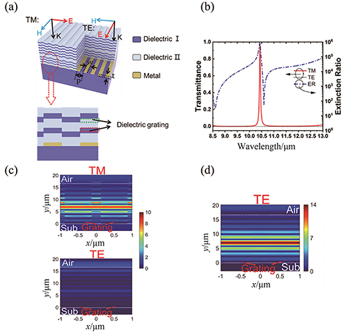
Figure 1.(a) Model of the SPF,the SPF with the subwavelength metal grating integrated on the substrate side (top) and partial enlarged view of the structure (bottom);(b) transmission spectra and PER of the SPF,the red solid line and black dashed line are the transmittances of the TM and TE,respectively,and the blue dotted line is the PER of the SPF;(c) the cross-sectional electric fields for the SPF at 10.4 μm;(d) the cross-sectional electric fields for the SPF at 10.6 μm of TE polarized light,the white dashed line is the dividing line between the upper and lower surfaces of the device,and the red dashed box is the grating position
All-dielectric F-P filters are extensively utilized in spectral detection and other domains owing to their highly tailored filtering capabilities,effortless integration,and superior spatial resolution[24-25]. A typical all-dielectric F-P filter with a central wavelength of can be expressed as Sub|(LH)m2L(HL)n,where Sub is the substrate,H is the high refractive index layer with optical thickness ,L is the refractive index layer with optical thickness ,and m and n denote the number of repetitions of the (HL) layer,and (LH)m and (HL)n are also known as distributed Bragg reflector (DBR). By adjusting the m and n values,high spectral resolution and transmittance can be obtained. Since the all-dielectric F-P filters are composed of isotropic dielectric films,they do not have polarization selection properties. Subwavelength metal gratings are considered as an excellent alternative to conventional polarization devices because of their superior polarization performance and ease of on-chip integration[26]. However,to further improve the polarization performance,it is generally necessary to reduce the metal grating period,increase the metal grating thickness or cascade multiple metal gratings. These methods inevitably increase the difficulty of device preparation and the inherent absorption characteristics of metal materials also affect the efficiency of the device.
In order to achieve high SR and PER simultaneously,we propose an SPF that integrates subwavelength metal gratings with an all-dielectric F-P filter. Figure 1(a) shows the model of the SPF with the subwavelength metal grating is integrated on the substrate side. It is well known that the F-P cavity has a mode selection effect,so it can continue to propagate through the F-P cavity only when the incident light frequency is consistent with the resonant frequency of the F-P cavity. The subwavelength metal grating selectively transmits TM polarized light and reflects TE polarized light,so the device has both wavelength-selective and polarization-selective functions. The rational design of the structure of the all- dielectric F-P filter makes it match the impedance of the metal grating,resulting in a device with higher transmission efficiency. Since the grating is located on the substrate,when the dielectric film is uniformly deposited on the substrate,each layer of the dielectric film will form two layers of dielectric gratings of equal thickness to the metal grating. And subwavelength dielectric gratings have different equivalent refractive indices for TM and TE polarization,so the introduction of dielectric gratings in all-dielectric F-P filters causes a shift in the transmission peak position of TM and TE polarized light. The polarization extinction ratio of the device can be further improved by using this peak shift.
The structure of SPF can be expressed as Sub|G(LH)32L(HL)5,where Sub is the Si substrate with ,H is 637 nm Ge with ,L is 1 183 nm ZnS with ,(LH) layer repetitions are 3 and 5,respectively. G represents an Ag grating whose structural parameters are period p=1 000 nm,width w=700 nm,thickness h=280 nm. In the following theoretical simulations,the refractive indices of Si substrate,Ge and ZnS keep constant as 3.47,4.16 and 2.24. Simulated results show that the SPF has the SR,PER and transmittance of 217, and 97% at 10.4 μm (in Fig. 1(b)),respectively. Figure 1(d) depicts the cross-sectional electric field diagram of the SPF with a subwavelength metal grating integrated on the substrate at 10.4 μm. When TM polarized light is incident,the electric field is mainly localized in the F-P cavity and the metal grating exhibits the properties of a dielectric film. F-P resonance is the reason for the high SR and transmission efficiency of the device. It is worth noting that the central wavelength of the device has a blue shift compared to the center wavelength of the DBR at 10.6 μm,which is due to the presence of the dielectric grating changing the equivalent refractive index of each film,causing the transmission peak to shift. When TE polarized light is incident,the reflection of DBR makes almost no electric field in the device,and coupled with the shielding effect of subwavelength metal gratings on TE polarized light,which leads to TE polarized light at this wavelength hardly continue to propagate further through the SPF. The valley of the extinction ratio in Fig. 1(b) at 10.6 μm is the transmission peak of TE polarization,and Fig. 1(d) is the electric field distribution at this wavelength,from which it can be seen that the SPF also produces a strong F-P resonance at 10.6 μm. Although the subwavelength metal grating can shield most of the TE polarized light,there will still be a very small amount of TE polarized light transmitted at this position,resulting in the PER to decrease. Therefore,increasing the number of DBR stacks can further improve the SR and PER of the device. For example,when the device structure is Sub|G(LH)42L(HL)6,the SR,PER and transmittance of the device are 695, and 92% respectively.
2 Results and discussion
The primary metrics for evaluating the performance of the SPF include the SR,PER,and peak transmittance. In this section,we will discuss several major factors that affect the performance of spectrally polarized spectroscopic devices and propose some methods to optimize the device performance. The SPF with the subwavelength metal gratings integrated on the substrate side can fabricate all-dielectric F-P filters based on already completed subwavelength gratings with low process difficulty,so this design was ultimately adopted to fabricate the SPF in this paper. In order to obtain spectrally polarized devices with excellent performance,we simplified and analyzed the model by means of the effective medium theory (EMT) and the effective interface method and optimized the structural parameters of the device by FDTD method.
Figure 2(a) depicts an effective interface method model of an SPF with a subwavelength metal grating integrated on the substrate,and the structure of which is composed of interface 1,interface 2,and an intermediate cavity layer. In this way,only multiple reflections in a single film layer need to be considered when we comprehensively analyze the performance of the entire device. Interface 1 consists of the top DBR,and interface 2 consists of the bottom DBR,substrate and subwavelength metal grating. and denote the reflection coefficient and transmission coefficient respectively. and denote the reflectance and transmittance respectively,where and .
, .
Figure 2.(a) Schematic diagram of the effective interface method;(b) schematic diagram of the effective medium theory;(c) equivalent refractive index of subwavelength Ag gratings at TE and TM polarized incidence,the red solid line and the blue solid line are the real and imaginary parts of the refractive index of the equivalent medium,respectively
As the device operates in transmission mode,our primary concern is its overall transmission .
,
the transmittance of the SPF can be fully determined by knowing only ,,,,and ,,.
At last,the total transmittance can be expressed as the following form:
.
The transfer matrix method can easily calculate the reflectance and transmittance of interface 1 and interface 2. However,since the transfer matrix method cannot be directly applied to the grating structure,the EMT is used to simplify the calculation by replacing the grating layer with a layer of uniform medium,as shown in Fig. 2(b). According to the EMT,the equivalent refractive indices of the grating layer at the incidence of TE polarized light and TM polarized light are:
,
where is the duty cycle of the grating (), and are the material refractive index and extinction coefficient,respectively,and the subscripts 1 and 2 represent the grating material and the material in the grating gap,respectively. If the material in the grating gap is air,then and . For example,we calculated the effective refractive index of a subwavelength Ag grating with a period of 400 nm and a duty cycle of 0.5 for TE and TM polarized light incidence using the refractive index of silver,as shown in Fig. 2(c). From the above results,it can be seen that when TM polarized light is incident,the subwavelength metal grating equivalent layer has a very small refractive index imaginary part,almost only having the real part of the refractive index,which has the characteristics of a dielectric film. And when TE-polarized light is incident,the subwavelength metal grating equivalent layer has a large refractive index imaginary part,which has properties similar to metals. The principle of metal grating polarization selection can be well understood by the above analysis: for TE polarized light,the grating layer is equivalent to a metal film,and most TE polarized light is reflected and absorbed; for TM polarized light,the grating layer is equivalent to a dielectric film,and most TM polarized light can be transmitted.
Changing the structural parameters of the grating changes its equivalent refractive index and thus changes R and T of interface 1 and interface 2. According to Eq.(4),the total transmittance of the SPF can be expressed as:
.
Therefore,the transmission wavelength,spectral resolution and polarization extinction ratio of the SPF can be optimized by regulating the period,duty cycle and thickness of the subwavelength grating,as well as designing the upper and lower reflective layer films.
The structure of the SPF can be expressed as Sub|G(LH)m2L(HL)n,the period,duty cycle and thickness of the grating are 1000 nm,0.5 and 300 nm,respectively,and m and n denote the number of repetitions of the (LH) layer. Figure 3(a) shows the transmittance of TM polarized light at different m and n. As m and n increase,the reflectivities of interface 1 and interface 2 will increase rapidly,and when the reflectances of interface 1 and interface 2 are approximately equal and sufficiently large,the SPF device will have maximum transmittance and spectral resolution.
Figure 3.(a) The TM transmittance of the SPF with different m and n;(b-c) transmittance and PER of the central wavelength when the grating period varies from 0.2 μm to 2 μm;(d-e) transmittance and PER of the central wavelength when the grating duty cycle varies from 0.1 to 0.9;(f-g) transmittance and PER of the central wavelength when the grating thickness varies from 50 nm to 500 nm,the red line represents the transmittance of TM polarized light,the black line represents the transmittance of TE polarized light,the blue line represents the polarization extinction ratio,and the green line represents the peak position of TM polarized light
A grating is a diffractive optical element that modulates light waves by changing the spatial structure of the propagation medium. The optical properties of the grating are determined by its diffraction level. When the grating period is much smaller than the incident light wavelength,the grating will only produce zero-level diffraction which develops many novel phenomena such as guided-mode resonance and surface plasmon resonance. The polarization-selective properties of subwavelength metal gratings also arise from the excitation and coupling of surface plasmon polaritons in the grating structure. Figure 3(b) shows the transmission spectrum,peak position and PER of the device as the grating period varies from 0.2 μm to 2 μm. As the grating period increases,the transmittances of both TM and TE polarized light increase,and the rate of increase of TE polarized light is much larger than that of TM polarized light. This is due to the fact that as the grating period increases,the condition that the grating period is much smaller than the subwavelength of the incident light wavelength is destroyed,so it causes the transmission of TE polarized light to increase. Moreover,the grating structure changes the equivalent refractive index of each film causing a blue shift of the peak position in the F-P cavity. As the period increases,the grating no longer satisfies the sub-wavelength condition (),resulting in a reduced degree of blue shift in the peak position. While a smaller grating period can certainly achieve a high degree of polarization extinction ratio,it also leads to a significant increase in device fabrication difficulty and manufacturing cost.
Duty cycle and thickness are two other vital parameters of gratings and are significant directions for optimizing SPFs. Figure 3(c) shows the transmission spectrum,peak position and PER of the device as the grating duty cycle varies from 0.1 to 0.9. According to Eq. (5),changing the duty cycle of the grating can directly change the refractive index of the grating's equivalent layer. For TM polarized light,its complex refractive index exists almost exclusively in the real part and increases with the duty cycle,and the transmittance is maximum when the refractive index matches best with the F-P cavity conductor. For TE polarized light,the imaginary part of its complex refractive index is larger and increases with the duty cycle,thus the TE transmittance decreases rapidly as the grating duty cycle increases. And adjusting the thickness of the grating directly changes the thickness of the grating's equivalent layer. The central wavelengths of TM and TE polarized light also vary with the change of duty cycle,which is caused by the change of equivalent refractive index of the DBR structure. When the transmission peaks of TE and TM polarized light coincide,the extinction ratio will show a significant decrease,such as when in the figure. Figure 3(d) shows the variation in the device’s transmission spectrum,peak position and PER as the grating thickness varies from 50 nm to 500 nm. For TM polarized light,the grating’s equivalent layer is a dielectric layer,and changing its thickness results in periodic changes in transmittance,and the maximum transmittance occurs when its equivalent admittance best matches the DBR. For TE polarized light,the grating equivalent layer is a metal layer. Obviously,the thicker the metal layer,the better its shielding effect on light. Therefore,as the grating thickness increases,the TE polarization transmittance rapidly decreases. In summary,the polarization performance of the device can be significantly improved by adopting a larger duty cycle and a thicker grating thickness when designing spectral polarized devices.
3 Fabrication procedure and experimental results
Benefiting from the design flexibility,we designed high-performance on-chip integrated SPFs,as shown in Fig. 4(a). The SPFs are composed of 10*10 array of SPF units,each of which consists of 4 polarization superpixels with different polarization angles (0°,45°,90°,135°),and each of which is composed of 4 spectral channels. This arrangement ensures that we can simultaneously obtain spectral information from 4 channels in 4 directions in one imaging,and in practice,the number of spectral channels can be increased or decreased as needed. To validate the design's feasibility,we fabricated subwavelength grating arrays and all-dielectric Fabry-Perot filters,respectively. We fabricated Ag gratings with the thickness of 280 nm on Si wafers by step lithography (Stepper,ASML PAS5500-350) and electron beam deposition (Sky Technology Development Co. Ltd. DZS 500) successively. We deposited 637 nm Ge and 1183 nm ZnS alternately on the Si wafers by electron beam deposition (Leybold ARES1110) to prepare the all-dielectric F-P filters. If required,it is possible to easily obtain all-dielectric F-P filters with multiple spectral channels by etching the cavity layer. Figures 4(b-c) show the scanning electron microscope (SEM,ZEISS Sigma 500) images of the grating array observed from the top and the cross section,respectively,which shows the excellent preparation of the grating. We used an infrared Fourier spectrometer (Bruker,Vertex 70) to measure the transmittance and polarization extinction ratio (blue line) of TM (red line) and TE (black line) polarized light of the subwavelength grating array,as well as the transmittance of the all- dielectric F-P filter (green line),as shown in Fig. 4(d). And the experimental results show that the grating has a PER exceeding 500 and a high transmission efficiency of 90% in the long wave infrared band. The all-dielectric F-P filter with the structure of Sub|(LH)22L(HL)3 also has a SR of 30 and a transmission efficiency of about 60% at 10.6 μm,and the SR can be easily increased by increasing the number of DBR stacks. Figure 4(e) shows the background noise of the measurement system and the TE polarized light spectrum of the grating,from which we can see that the TE polarized light intensity and the background noise are in the same order of magnitude in the long-wave infrared band,at this time,the polarization extinction ratio of the grating reaches the measurement limit of the system,and the actual extinction ratio of the grating will be higher.
Figure 4.(a) Schematic diagram of the on-chip integrated SPFs,each of which consists of four polarization superpixel with polarization angles of 0°,45°,90°,and 135°,respectively,each polarization superpixel is composed of 4 spectral channels,which are represented by small squares of different colors in the figure;(b) the SEM image of the grating;(c) the cross-sectional SEM image of the grating;(d) experimental spectrum and PER of grating and all-dielectric F-P filter;(e) background noise of the measurement system and TE polarized light spectrum of the grating
Infrared spectral polarization imaging (IR-SPI) can distinguish background and targets based on thermal radiation differences regardless of weather conditions and sunlight,while the addition of spectral and polarization information greatly improves the imaging system's ability to identify specific targets in complex environments,such as polarization and fusion imaging. Polarization information is usually described by the Stokes parameters (,,,):
.
In practical application, is usually set to zero because the component of circular polarization is very small. Thus,the Stokes parameters of the target can be obtained by rotating the polarizer or using an array of polarizers with different angles,and further adding a filter to the imaging system can obtain the polarization information of a specific wavelength. And using the Stokes parameters,the degree of polarization (DOLP) and angle of polarization (AOP) of the target can be calculated.
.
However,using our designed SPFs and detector for integration can eliminate these tedious steps. The Stokes parameters of four spectral channels can be obtained in one imaging,which greatly simplifies the complexity of the SPI system. The experiment verifies the feasibility of SPFs applied to the field of SPI and provides a new way to miniaturize real-time spectral polarization imaging systems.
4 Conclusions
In summary,we have designed an ultra-high performance SPF by integrating subwavelength metal gratings on all-dielectric F-P filters. When TE polarized light is incident,the metal layer property of the subwavelength metal grating enables it to reflect TE polarized light efficiently,and when TM polarized light is incident,the dielectric layer property of the subwavelength metallic grating enables it to transmit TM polarized light efficiently,with F-P resonance dominating the mode. The device enables both wavelength and polarization selection,and the two characteristics can be independently regulated. The experimental results show that our grating has a PER of over 500 and a transmission efficiency of up to 90% and the all-dielectric F-P filter has a SR of 30 and a transmission efficiency of 60% for the long-wave infrared band,which manifests its potential in the field of SPI. At the same time,due to its compactness,integration,miniaturization and compatibility,our spectral polarization device is expected to provide high-performance real-time spectral and polarization monitoring for more advanced applications and offer a new solution for the development of multi-mode detection chips.
[9] W NAN, Z LI-FU, D CHU-BO et al. Beer Freshness Detection Method Based on Spectral Analysis Technology. Spectroscopy and Spectral Analysis, 40, 2273-7(2020).
[10] H LUO, J CAO, X GAI et al. Industrial Vision Based on Polarization Imaging and Its Key Technologies. Laser & Optoelectronics Progress, 59, 1415003(2022).
[13] LI Guangde, L Dongqing, W Yi et al. Research Status and Progress of the Thermal Infrared Camouflage Technology. Infrared Technology, 41, 495(2019).