
Nian Zhang, Baoxing Xiong, Xiang Zhang, Xiao Yuan. Multiparameter encrypted orbital angular momentum multiplexed holography based on multiramp helicoconical beams[J]. Advanced Photonics Nexus, 2023, 2(3): 036013
- Advanced Photonics Nexus
- Vol. 2, Issue 3, 036013 (2023)
Abstract
Keywords
1 Introduction
Optical holography is one of the promising technologies for information encryption and storage.1 In traditional holography, the different physical dimensions of light, such as phase, polarization, and wavelength, have been implemented for multiplexing multiple data in a single multiplexed hologram to improve the capability of security encryption.2
Recently, OAM multiplexed holography has been demonstrated and experimentally implemented as an independent information channel that can preserve the OAM property and achieve the OAM selectivity in the reconstructed images.15
In this work, multiramp helical-conical orbital angular momentum (MHC-OAM) multiplexed holography is proposed and implemented. The four parameters of the MHC beam can be independently modulated, namely, TC, the number of multiramp mixed screw-edge dislocations , the constant , and the normalized factor . The MHC-OAM mode selectivity has been investigated based on the number of multiramp mixed screw-edge dislocations , the constant , and the normalized factor . According to these parameters, the multidimensional multiplexed holography can be obtained. The feasibility of the MHC-OAM multiplexed holography in different dimensions is verified in experiments. This method shows the huge application possibilities in information encryption and storage.
Sign up for Advanced Photonics Nexus TOC. Get the latest issue of Advanced Photonics Nexus delivered right to you!Sign up now
2 Principle and Methods
2.1 Principle of MHC-OAM Multiplexed Holography
The phase function of the MHC beams is written as28
The spatial frequency distribution of the MHC beams based on the Fourier integral theorem is expressed as29
![]()
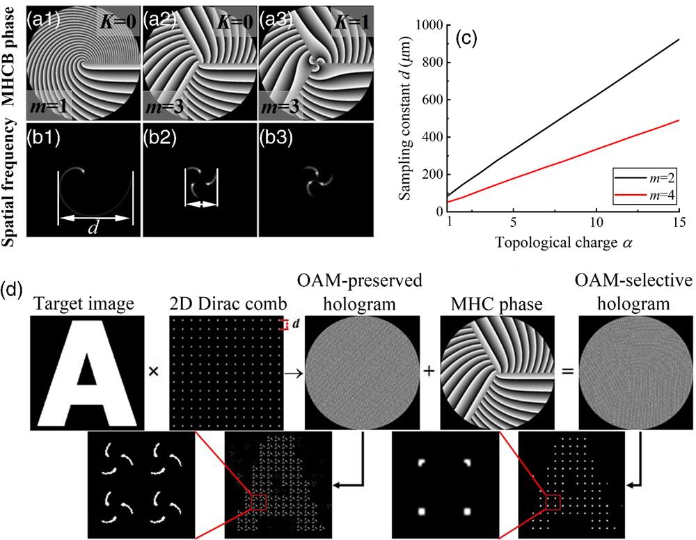
Figure 1.(a1)–(a3) Phase distributions of the MHC beams. (b1)–(b3) Simulation of the spatial frequency distributions of the MHC beams. (c) Relationship between the TC and sampling constant
In a computer-generated hologram (CGH), a Fourier pair is formed between the electric field of the image plane and holographic plane, so the electric field of the reconstructed image is16
The design principle of the MHC-OAM holography is shown in Fig. 1(d). According to the adaptive weighted Gerchberg–Saxton (AWGS) algorithm, an OAM-preserved hologram is obtained, as depicted in the middle part of Fig. 1(d). Notice that the MHC beam is preserved in each pixel of the reconstructed image. From the right part in Fig. 1(d), the phase function of an MHC beam is superimposed into the OAM-preserved hologram, resulting in the generation of an OAM-selective hologram. Due to OAM conservation, the Gaussian spots with a stronger intensity distribution in the desired holographic image are obtained only for a given incident MHC phase mode with . Finally, the multiplexed hologram can be obtained from the superposition of multiple selective holograms.
2.2 MHC-OAM Mode Selectivity
The mode selectivity of MHC beams with the constant , the number of multiramp mixed screw-edge dislocations , and the normalized factor in image reconstruction are illustrated in Fig. 2. The encoded phase parameters of the hologram are fixed as , , , and . First, we demonstrate the MHC mode selectivity under the constant , as shown in Fig. 2(a). When the decoded phase mode with , , , illuminates the hologram, the Gaussian spot with stronger intensity is obtained. However, the reconstructed light field with lower intensity is formed when the incident decoded MHC beam with , which can be regarded as background intensity and ignored. Figure 2(b) shows the effect of the number of multiramp mixed screw-edge dislocations on the mode selectivity. Similarly, when the hologram is illuminated by the decoded phase mode with , the desired Gaussian spot is obtained. Otherwise, the peak intensity of the mode with or 4 is lower than that of the mode with . The relationship between the reconstructed peak intensity and the normalized factor is shown in Fig. 2(c). It can be seen that the peak intensity is influenced by the decoded phase with different normalized factors . If the difference between decoding and encoding is more than 0.1 mm, the reconstructed peak intensity can be neglected. In this case, the multiplexing interval of can be set to . The reconstructed intensity distributions with different are shown in Fig. 2(d).
![]()
Figure 2.MHC-OAM mode selectivity. (a) Mode selectivity of the constant
In order to select the appropriate parameters and for the multiplexed holograms and to ensure that the multiplexed results have a good signal-to-noise ratio (SNR), the corresponding OAM-selective holograms are designed using OAM selectivity. The effect of the number of multiramp mixed screw-edge dislocations on the SNR is shown in Fig. 3(a). The MHC phase with is superposed on the MHC-OAM-preserved hologram, resulting in the generation of an MHC-OAM-selective hologram, and , 2, 3, 4, 5 are the decoding phase parameters of incident MHC beams. When the incident MHC beam with parameter illuminates the hologram, we can decode the target image with a relatively high SNR, as the parameter of the incident MHC beam can match better with the design value of . On the contrary, we get the reconstructed image with poor SNR, and the reconstructed image will be hidden. Under the promise of obtaining a high SNR, the difference of in holographic multiplexing can be chosen as 1. The SNR as a continuous function of the decoded normalized factor is depicted in Fig. 3(b). When the decoded normalized factor is close to the encoded normalized factor, the reconstructed result with a relatively high SNR is obtained. Under the promise of a high SNR, the difference between the normalized factors of the encoded and the decoded MHC phase modes is required to exceed 0.1 mm.
![]()
Figure 3.(a) SNR as a function of the number of multiramp mixed screw-edge dislocations. (b) SNR as a function of the normalized factor.
3 Results and Discussion
The schematic diagram of the experimental setup of MHC-OAM holography is shown in Fig. 4. An He–Ne laser (Research Electro-Optics, R-31007) with a wavelength of 633 nm and a power of 0.8 mW is used as the light source. The laser beam is expanded and collimated by a objective and a lens L1 with a focal length of 400 mm. An aperture is used to adjust the size of the incident beam matching the phase-only spatial light modulator (SLM, Hamamatsu-X13138 series-07, , pixel pitch of ). Since the SLM is only sensitive to the horizontal polarized component of the incident beam, a polarizer is inserted between the aperture and the SLM to generate a horizontal polarized beam. The beam is modulated by the SLM and passes through a lens L2 with the focal length of 100 mm to a CCD (GS3-PGE-91S6M-C, , pixel pitch of ) used to capture the reconstructed holographic image. In this work, the experimental system is simplified, since we have only one SLM. The hologram pattern is not directly illuminated by an MHC beam. Alternatively, the decoded MHC phase distribution is superimposed into the hologram, which is illuminated by a planar beam, as shown in Fig. 4(a). In the decrypted process, the hologram used is represented as the superposition of the decoded MHC phase and the MHC-OAM hologram, so the mathematical phase-only hologram can be described as
![]()
Figure 4.(a) Schematic diagram of the experimental setup of MHC-OAM holography. L1 and L2, lens; A, aperture; P, polarizer; BS, beam splitter; and SLM, spatial light modulator. (b) The hologram loaded into the SLM contains the decoded phase and OAM hologram.
3.1 m- or r0-Encrypted MHC-OAM Multiplexed Holography
According to the results in Sec. 2, the number of multiramp mixed screw-edge dislocations and the normalized factor can be used as independent channels for multiplexed holography. The MHC-OAM multiplexed holography with - and -encryption is implemented in the experiment. Figure 5 shows the schematic diagram of the -encrypted MHC-OAM multiplexed holography. The four Arabic numbers “1,” “2,” “3,” and “4” are set as target images and encoded into four OAM preserved holograms using the AWGS algorithm, respectively. Then the four MHC phase modes with the TC of 8, the constant , the normalized factor of 1 mm, and the number of multiramp mixed screw-edge dislocations of 4, 5, 6, and 7 are superimposed into the OAM-preserved hologram, leading to the four OAM selective holograms, respectively. These four OAM selective holograms can be superimposed into one OAM-multiplexed hologram, as shown in Fig. 5(a). The feasibility of the -multiplexed holography is numerically simulated (Note S2 and Fig. S2 in the Supplementary Material). The experimental results are shown in Figs. 5(b)–5(e). When the MHC-OAM multiplexed hologram with the key is illuminated by the different incident MHC beams with , , , and , four distinct images are reconstructed, respectively. The pixel intensity fluctuations in the reconstructed images may originate from three factors: inadequate phase modulation of the SLM, the uniformity of the incident beam, and nonuniform photon sensitivity of the pixelated CCD camera. When the multiplexed hologram is illuminated by a planar beam, four images appear simultaneously and are indistinguishable from each other, as shown in Fig. 5(f). The results exhibit that four images can be encrypted and decrypted from one multiplexed hologram under the same TC of the MHC beams.
![]()
Figure 5.Schematic diagram of MHC-OAM-multiplexed holography designed with key
In order to enhance the capacity of holographic multiplexation, the normalized factor is used in OAM-multiplexed holography. The design process of the -encrypted MHC-OAM-multiplexed holography is shown in Fig. 6(a). Four images with the letters “C,” “O,” “P,” and “E” are encrypted into a single MHC-OAM-multiplexed hologram, where the normalized factors of , 0.6, 0.7, and 0.8 mm are adopted to decrypt each image, respectively. The other coding parameters are fixed as , , and . In the decryption process, each image can be reconstructed when the incident MHC beam with . The influence of parameter on MHC-OAM-multiplexed holography is numerically investigated (Note S3 and Fig. S3 in the Supplementary Material). It is clear to see that the reconstructed target images have a relatively low SNR due to the spatial overlap of MHC modes (Table S1 in the Supplementary Material). In order to reduce the overlap between MHC modes, the target images with larger sampling constants are numerically simulated (Table S2 and Fig. S4 in the Supplementary Material). The experimental results are shown in Figs. 6(b)–6(e). In this case, the MHC-OAM-multiplexed holography with the -encryption is implemented, demonstrating that the normalized factor can be used as an independent information channel. The multiplexing crosstalk is analyzed in the holographic reconstruction (Note S4 and Fig. S5 in the Supplementary Material). In addition, the crosstalk can have originated from the noise of the CCD, the uniformity of the incident beam, or the limitation of the sampling point. In CGH, the MHC-OAM hologram and target image are discretely sampled, which is limited by the pixel pitch of the SLM and the spatial frequency of the MHC beam. Although the iteration algorithm can optimize the intensity value of each sampling point, the area between the sampling points is completely unrestricted. If the phase difference between the adjacent sampling points is chose to , the noise may appear.
![]()
Figure 6.Schematic diagram of MHC-OAM-multiplexed holography designed with key
On the other hand, the impact of TC on the MHC-OAM-multiplexed holography is numerically characterized (Note S5 and Fig. S6 in the Supplementary Material). Our numerical results show that the use of MHC beams with a larger TC difference in the holographic multiplexing can yield a lower crosstalk. Moreover, it should be mentioned that the effect of constant on the reconstruction of MHC-OAM-multiplexed holography exhibits a good SNR (Note S6 and Fig. S7 in the Supplementary Material). The above results show that using MHC modes with a smaller TC difference or a smaller normalized factor difference produces a higher crosstalk. Therefore, the selection of TC and the normalized factor needs special consideration in the design of holographic multiplexing. Meanwhile, our results suggest that the selection of larger sampling constants is beneficial to improve the SNR.
3.2 X-K-Encrypted MHC-OAM-Multiplexed Holography
In this section, the combination of the parameter and the constant will be demonstrated in different multiplexing channels. Three modulation parameters of the MHC beams, namely, TC, , and can be used as independent degrees of freedom, so the parameter is chosen as any one of the above three parameters.
The -encrypted MHC-OAM-multiplexed holography is shown in Fig. 7. Two different TCs ( and 5) and two different constants ( and 1) are used to encode the four images with the letters “D,” “A,” “T,” and “E.” One -encrypted MHC-OAM-multiplexed hologram can be obtained by superimposing the four OAM selective holograms generated from the OAM-preserved holograms and four MHC phase modes with , , , and . Here the TC and the constant together determine the encrypted and decrypted images. The four images can be reconstructed when the multiplexed hologram is illuminated by different MHC beams with , , , and , respectively, as shown in Figs. 7(b)–7(e).
![]()
Figure 7.Experimental reconstruction results of the
The MHC-OAM-multiplexed holography based on the number of multiramp mixed screw-edge dislocations and the constant is implemented under the same TC and the same normalized factor. The design process is shown in Fig. 8(a). The four images with the letters “W,” “O,” “R,” and “D” are encrypted by the different number of multiramp mixed screw-edge dislocations ( and 5) and the different constants ( and 1). The reconstructed results are shown in Figs. 8(b)–8(e). The encoded images can be reconstructed when the incident MHC beams with inverse TC, and the specific number of multiramp mixed screw-edge dislocations, the constant, and the normalized factor are used. Furthermore, the -encrypted MHC-OAM-multiplexed hologram is designed, as shown in Fig. 9(a). The four letters “L,” “I,” “F,” and “E” are encoded by the four different MHC phase modes with the same TC (), the same number of multiramp mixed screw-edge dislocations (), two different normalized factors ( and 1 mm), and two different constants ( and 1). The experimental results are shown in Figs. 9(b)–9(e), where each image is reconstructed from the suitable incident MHC beam.
![]()
Figure 8.The experimental reconstruction results of the
![]()
Figure 9.Experimental reconstruction results of the
In addition, the -encrypted MHC-OAM-multiplexed holography is further investigated. Four images with Arabic numbers “5,” “6,” “7,” and “8” are used and encrypted into four OAM holograms. The four MHC phase modes with , , , and are superimposed into the above four OAM holograms, resulting in four OAM selective holograms. The MHC-OAM-multiplexed hologram with the -encryption is designed in Fig. 10(a). Each image can only be reconstructed by the incident MHC beam with , as shown in Figs. 10(b)–10(e).
![]()
Figure 10.Experimental reconstruction results of the
3.3 α-m-Y-Encrypted MHC-OAM-Multiplexed Holography
Here the parameter is chosen as the normalized factor and the constant . First, the principle of -encrypted OAM-multiplexed holography is illustrated in Fig. 11(a). The nine images with Arabic numbers 1 to 9 are encoded into nine holograms, then nine different MHC phase modes with the constant , TC values of , 6, and 12, values from 3 to 5 with the interval of 1, and values from 0.5 to 0.7 mm with the interval of 0.1 mm are added to the above nine holograms, resulting in the nine OAM selective holograms. The -encrypted MHC-OAM-multiplexed hologram is obtained by superimposing all selective holograms. In the decryption process, the encrypted images can be reconstructed by the suitable incident MHC beams with , as shown in Fig. 11(b). Thus the combination of these parameters provides a high level of information security.
![]()
Figure 11.Experimental reconstruction results of the
The TC , the number of multiramp mixed screw-edge dislocations , and the constant are used to increase the number of multiplexed channels. The 12 images from 1 to 6 and A to F are encrypted into different OAM-preserved holograms. Four different TCs , three multiramp mixed screw-edge dislocations (, 4, 5) and two constants (, 0) are used to encrypt the above 12 images. The encoded phase mode of each image is shown in Fig. 12(a), and the experimental reconstruction results are shown in Fig. 12(b).
![]()
Figure 12.Experimental reconstruction results of the
3.4 α-m-r0-K-Encrypted MHC-OAM-Multiplexed Holography
The four parameters of the MHC beam are independent of each other and can potentially be used for holographic multiplexing in four dimensions. A four-parameter dimensional multiplexed holography can be achieved by encrypting 16 images in different channels with these parameters. Four different TCs , four different multiramp mixed screw-edge dislocations from 4 to 7 with the step of 1, four different normalized factors from 0.6 to 0.9 mm with the interval of 0.1 mm, and two different constants (, 1) are used to encode these 16 images. The 16 images are chosen from 0 to 9 and A to F. Here the parameters of each encoded image are shown in Fig. 13. The 16 OAM-selective holograms can be generated by encoding the different MHC phase modes into the corresponding OAM-preserved holograms. The -encrypted MHC-OAM-multiplexed holography can be obtained by superposing those 16 selective holograms. Each target image can be reconstructed when the suitable MHC beams with illuminate the multiplexed hologram. The experimental results are presented in Fig. 14.
![]()
Figure 13.The encrypted images are encoded by the parameters
![]()
Figure 14.Experimental reconstruction results of the
4 Conclusion
In summary, the MHC-OAMmultiplexed holography is proposed and experimentally implemented by introducing the number of multiramp mixed screw-edge dislocations, the normalized factor, and the constant as new degrees of freedom. The MHC beams modulated with different parameters can be utilized as information encryption or decryption channels, which enhance the capability of holographic multiplexation. In the experiments, we have successfully realized 4-, 9-, 12- and 16-channel multiplexing by the combination of the four parameters of MHC beam. The results show that the encrypted image can be correctly reconstructed when the MHC-OAM hologram is illuminated by the incident MHC beam with an inverse TC, a customized number of multiramp mixed screw-edge dislocations, the normalized factor, and the constant , while there is no image reconstructed with false MHC beam. The multiplexed holography proposed in this work can significantly improve the capability of the information encryption and storage and has potential applications in communication, 3D display, etc.
Nian Zhang received his MS degree in optical engineering from the School of Optoelectronic Science and Engineering, Soochow University, Suzhou, China, in 2020. He is currently a PhD student in optical engineering at the School of Optoelectronic Science and Engineering, Soochow University, Suzhou, China. His research interests are holography and vortex beams.
Baoxing Xiong received his MS degree in optical engineering from the School of Optoelectronic Science and Engineering, Soochow University, Suzhou, China. He is an assistant researcher at the School of Optoelectronic Science and Engineering, Soochow University, Suzhou, China. His research interest is photothermal refractive glass.
Xiang Zhang received his MS and PhD degrees in optical engineering from the National Laboratory for Optoelectronics, Huazhong University of Science and Technology, Wuhan, China. He is a professor at the School of Optoelectronic Science and Engineering, Soochow University, Suzhou, China. His research interests are the preparation of photothermal refractive glass and Bragg volume diffractive devices, the theory and preparation of micro-nano-structure optical devices, advanced solid-state laser technology, and beam control.
Xiao Yuan is a Distinguished Professor at the School of Optoelectronic Science and Engineering, Soochow University, Suzhou, China. He was a visiting scientist at the University of Maryland from 1995 to 1997 and worked at the School of Optoelectronic Science and Engineering of Huazhong University of Science and Technology from 2002 to 2008. His research interests include high-power lasers and their applications, micro-nano-optical devices and technologies, laser materials and devices, nonlinear optics, and laser plasma physics. He has coauthored more than 100 publications in peer-reviewed journals.

Set citation alerts for the article
Please enter your email address
© Copyright 2018-2021 | Chinese Laser Press. All Rights Reserved 沪ICP备15018463号-20