1Joint Institute for Measurement Science, Beijing 100084, China
2The State Key Lab of Precision Measurement Technology and Instruments, Department of Precision Instruments, Tsinghua University, Beijing 100084, China
3Department of Physics, Tsinghua University, Beijing 100084, China
4National Institute of Metrology, Beijing 100013, China
Yu Bai, Bo Wang, Chao Gao, Jing Miao, Xi Zhu, Lijun Wang, "Fiber-based radio frequency dissemination for branching networks with passive phase-noise cancelation," Chin. Opt. Lett. 13, 061201 (2015)
Copy Citation Text
We demonstrate a new fiber-based radio frequency (RF) dissemination scheme suitable for a star-shaped branching network. Without any phase controls on the RF signals or the use of active feedback-locking components, the highly stable reference frequency signal can be delivered to several remote sites simultaneously and independently. The relative frequency stabilities of and are obtained for a 10 km dissemination. This low cost and scalable method can be applied to a large-scale frequency synchronization network.
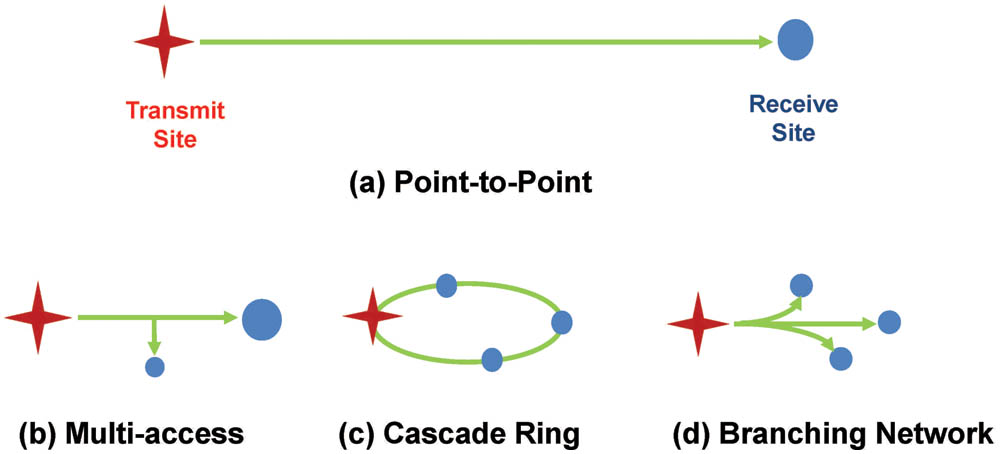
Over the past two decades, the highly stable dissemination of time and frequency signals via optical fiber links has developed considerably and shown broad application prospects[1–3]. Different schemes, such as optical frequency dissemination[4,5], radio frequency (RF) dissemination[6,7], and optical frequency comb signal dissemination[8,9] have been proposed and demonstrated. However, almost all of these schemes have a common “point-to-point” structure, as shown in Fig. 1(a), meaning that there is only one receiving site connected to a single transmission site. Despite its high stability, the limited accessibility greatly limits further applications of the fiber-based frequency dissemination technology.
Figure 1.Topological structure diagram of different fiber-based frequency dissemination schemes. (a) The conventional point-to-point dissemination scheme. (b) Multi-access at an arbitrary point along the fiber link. (c) Cascade dissemination scheme with relay stations. (d) Branching fiber network dissemination scheme.
To overcome this main drawback, fiber-based, multi-access, ultrastable radio and optical frequency dissemination schemes have been proposed and demonstrated[10–15]. Using this method, a highly synchronized RF modulation signal or the optical signal itself can be recovered at any arbitrary point along the fiber link, as shown in Fig. 1(b). To extend the frequency dissemination distance, cascaded frequency disseminations [see Fig. 1(c)] have been demonstrated[16]. Along with the developments of related technologies and improvements in observation accuracy, more and more large-scale scientific and engineering facilities, such as radio astronomy arrays[17–20] and deep space navigation (DSN) measurement and control networks[21,22], require the dissemination of reference frequency signals from a certain center site to multiple remote sites over a star-like branching fiber network, as shown in Fig. 1(d). For example, let us look at the Square Kilometre Array (SKA) project. It represents one of the largest and most challenging timing and synchronization networks being used today[23]. Thousands of antennas are distributed as a symmetrical array around the core, and are all phase locked to the center reference clock[24]. The key challenge of all fiber-based frequency dissemination schemes is how to compensate for the fiber-induced phase fluctuation. To our knowledge, including the recently demonstrated optical frequency dissemination technique for a branching optical fiber network[25], almost all existing schemes are developed based on the active phase-locking method proposed in 1994 by Ma et al.[1]. The cost and reliability are the main limiting factors for the large-scale application of conventional, active, fiber-based frequency dissemination schemes.
In this Letter, we propose and demonstrate a new fiber-based RF dissemination scheme suitable for a branching network. Using the passive phase-noise cancelation method, the fiber-induced phase fluctuation can be compensated for without an active feedback-locking loop, and the highly stable reference frequency signal can be delivered to remote sites simultaneously and independently. For a 10 km distance dissemination, the relative frequency stabilities of and are obtained. The scheme can dramatically simplify the setup and reduce the cost. These advantages make it suitable for constructing the frequency synchronization networks for DSN and the SKA.
Figure 2 shows the schematic diagram of the passive frequency dissemination for the branching network experiment. The basic principle of this method can be summarized as the “1f–3f” method. Two phase-locked RF signals whose frequencies have triple relations are all transmitted to remote sites. The “1f” signal is sent back to the local site and then reflected back to the remote sites again. Thus, the fiber-induced phase fluctuation, which is slower than the round trip delay, can be passively compensated by mixing the received “f” and “3f” signals at each remote site.
Figure 2.Schematic diagram of the fiber-based RF dissemination scheme for branching networks with the passive phase-noise cancelation method. EDFA: erbium-doped fiber amplifier; FC: fiber coupler; OSC: oscilloscope; WDM: wavelength division multiplexer; PD: photo-diode; BP: bandpass filter.
In the laboratory demonstration, the branching network consists of one local site, three remote sites (C, D, E), and three fiber spools with lengths of 2, 3, and 5 km. For the convenience of the relative frequency stability measurement, the entire system is placed in the same lab.
At the local site, the 100 MHz frequency signal of a commercial hydrogen maser is employed as the reference frequency of the entire branching network. It can be expressed as . Two phase-locked dielectric resonator oscillators with frequencies of 3 and 1 GHz are phase locked to , and can be expressed as and , respectively. The frequency and phase of and have fixed, three-fold relationships. They are used to modulate the amplitudes of lasers A and B, whose wavelengths are at 1542 and 1547 nm, respectively. After passing a fiber coupler and a circulator, two modulated laser signals are coupled into the same fiber link and delivered to all remote sites. The output power of each laser is about 10 mW.
The structures of the remote sites are almost the same except for the wavelengths of their own laser modules. Here, we choose the remote site C to explain the concept. At remote site C, a wavelength division multiplexer is used to separate the received laser signals. The disseminated RF signals are recovered by two high-speed photo-diodes (PDs). They can be expressed as where and represent the fiber link-induced phase fluctuations for the 3 GHz signal and the 1 GHz signal , respectively. As mentioned previously, and have three-fold relationships for both frequency and phase, and they are disseminated in the same fiber simultaneously. By neglecting the influence of chromatic dispersion and the phase fluctuations that are faster than the round trip delay, we can assume that . The recovered frequency signal is used to modulate the amplitude of another laser C, whose wavelength is 1550 nm. The modulated laser signal is then sent back to the local site and reflected back to remote site C again with the help of two fiber circulators. Due to the optical power losses caused by several fiber couplers (50/50 ratio) along the branching network, an erbium-doped fiber amplifier is used at the local site to amplify the optical powers of all signals sent back from the remote sites. The amplification gain can be adjusted accordingly to be compatible with the dissemination distance. For more remote sites, more than one amplifier may be used. In the proposed situation, the total amplification gain is 13 dB.
At remote site C, after being detected by another PD, the recovered 1 GHz frequency signal can be expressed as
By simply mixing down the signals and , we can obtain a 2 GHz signal:
We choose a high-linearity mixer (Marki T3-03) to reduce the impact of the second harmonic of the 1 GHz signal and used a bandpass filter centered at 2 GHz to pick out the mixed signal. We can see that the fiber-induced phase fluctuation has been passively compensated.
Considering the requirements of status monitoring and error diagnosis in practical applications, we also add an additional monitoring port. The optical power and RF waveforms of all of the remote sites can be monitored with an oscilloscope at the center station.
To distinguish the round trip signals of each remote site, the laser modules’ wavelengths inside remote sites D and E are chosen as 1552 and 1555 nm, respectively. The chromatic dispersion limitation can be quantitatively estimated[26–28]. For a 10 km fiber dissemination in the proposed scheme, the phase time delay difference is . Supposing a diurnal temperature fluctuation of 30 K, and the biggest difference of the laser wavelengths of 13 nm (1542 nm for laser A and 1555 nm for laser E), the phase time delay difference of the frequency signals is about 5.5 ps, which corresponds to the dissemination stability of with an integration time of a half day. With modern dense wavelength division multiplexing technology[29,30], the laser carriers’ wavelengths can be as near as 0.4 nm. This will significantly reduce the chromatic dispersion effect on the dissemination stability and expand the quantity of the remote sites to several dozens or even hundreds.
By mixing and at the local site, we can get . To measure the dissemination stability, we just mix and down to a DC voltage and record it with a 7-1/2 digit multimeter (Keithley 2001). Thus, we can analyze the phase error between and , and calculate the Allan deviation with the help of a commercial software program called Stable32. We also compare and to measure the dissemination stability of the free-running fiber link. Similar procedures are performed for remote sites D and E. In order to verify that all remote sites are independent and the proposed scheme is feasible for a branching network application, all of these measurements are carried out simultaneously. Figure 3 shows the measured Allan deviation results. Using the passive phase-noise cancelation method, dissemination stabilities of and are achieved for remote site E (10 km away from the local site). The dissemination stabilities of the free-running fiber link are and . In the preliminary demonstration, the results have already shown a significant improvement in the dissemination stability, which can well meet the reference frequency synchronization requirements of most applications at the present stage. A series of further experiments will be conducted, including reliability testing and noise analysis, in order to verify that the scheme can be really applied in large-scale applications such as the SKA.
Figure 3.Measured relative frequency stabilities of frequency signals at three remote sites C, D, and E with and without the fiber-induced phase fluctuation passively compensated.
As a potential application example, we briefly introduce the Beijing regional time and frequency synchronization network, which is under construction[31]. As shown in Fig. 4, the synchronization network can be separated into three parts: time keeping stations, coordinating station, and client sites. The time keeping points are the institutes that maintain the national or regional official times. Using the conventional, active compensation scheme[7], a time keeping station can perform frequency comparison and transmit its time-frequency signal to a central coordinating station. Here, the received time keeping signals can be compared in real time to generate a coordinated time and frequency signal. Then, the coordinated signal can be disseminated back to each time keeping station and forwarded to all user clients via the present passive compensation method. As one transmitting module can be linked with multiple remote sites, the expansion of future dissemination channels (the expansion of the clients) will not have any significant impact on the coordinating station’s basic structure.
Figure 4.Schematic diagram of a regional time and frequency synchronization network.
In conclusion, we demonstrate a new fiber-based RF dissemination scheme for a branching network. Using our method, stable, distributed RF signals can be simultaneously and independently disseminated to many different remote sites from one central station. More importantly, the method is scalable and expandable, with the benefit that the addition of new groups of client sites will not cause significant changes at the central dissemination site. It is hoped that this method will be applied in large-scale time and frequency networks.
Yu Bai, Bo Wang, Chao Gao, Jing Miao, Xi Zhu, Lijun Wang, "Fiber-based radio frequency dissemination for branching networks with passive phase-noise cancelation," Chin. Opt. Lett. 13, 061201 (2015)