
Ju Wang, Ting Jia, Shuaishuai Wang, Tianyu Li, Chuang Ma, Tianyuan Xie, Yang Yu, Jinlong Yu. Wavelength synchronization technology for UDWDM-PON transmitter based on injection locking[J]. Chinese Optics Letters, 2021, 19(1): 010602
- Chinese Optics Letters
- Vol. 19, Issue 1, 010602 (2021)
Abstract
1. Introduction
Due to the rapid expansion of network scale and the continuous growth of capacity requirements, the technology research for large-scale access networks has been executed[
In recent years, many researches were established on how to ensure the stability of wavelength spacing in UDWDM systems. For instance, Lee et al. used the Rayleigh backscattering characteristics to control the wavelength of the tunable laser[
In order to ensure the wavelength stability spacing of up- and downstream easily, a technology of wavelength synchronization is proposed by establishing wavelength references in this Letter. In this scheme, user wavelength references are provided by an optical frequency comb (OFC) source and separated by injection locking DFB lasers. Baseband data transmission is realized by selective wavelength modulation, where odd wavelengths are used as downlink carriers and even wavelengths as uplink carriers. In the optical network unit (ONU), the uplink optical carriers are demultiplexed using injection-locked semiconductor lasers, which ensure the consistency of channel spacing between the up- and downstream users. In order to further guarantee the synchronization of wavelengths, this scheme adopts automatic wavelength reference locking and tracking technology for each channel, which automatically controls the DFB laser wavelength to track the reference in real time. The active filter achieved by injection locking DFB lasers solves the problem of low accuracy and the difficulty in flexible application due to the fixed bandwidth.
Sign up for Chinese Optics Letters TOC. Get the latest issue of Chinese Optics Letters delivered right to you!Sign up now
2. Principle
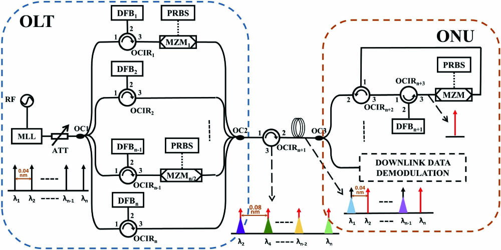
The scheme of wavelength synchronization for the UDWDM-PON transmitter is shown in Fig. 1. All of the wavelength references are provided by mode-locked lasers (MLLs) in this scheme. In the optical line terminal (OLT), the optical spectrum of the MLL is divided into multiple references by injecting into semiconductor lasers. As shown in Fig. 1, after being separated by an optical coupler (OC1), the references of the MLL are divided into two groups of channels. The odd channels are modulated by a Mach–Zehnder modulator (MZM) using intensity modulation to carry baseband signals. In the experimental setup, 500 Mbit/s pseudo-random binary sequence (PRBS) codes consisting of non-return-to-zero (NRZ) are transmitted in 5 GHz spacing (0.04 nm in wavelength).
![]()
Figure 1.Downlink and uplink wavelength references synchronization scheme in UDWDM-PON. MLL, mode-locked laser; RF, radio frequency; MZM, Mach–Zehnder modulator.
The even channels are used as upstream optical carriers. This scheme provides services to maximize the user number with relatively slow data rate to take full advantage of the bandwidth resource of optical fibers. The signal of downstream and wavelength references of the uplink are cross distributed for reducing possible crosstalk. The uplink channels are separated at the same time, which provide larger channel spacing for each user and contribute to the synchronization. Then, the two groups of channels are coupled together by OC2, ports 1 and 2 of the optical circulator OCIR, and transmit through the optical fiber.
Two groups of channels are coupled together and transmit through the optical fiber, where the adjacent carriers have 5 GHz (0.04 nm in wavelength) channel spacing. In the ONU, the uplink carriers are filtered by injection locking semiconductor lasers through ports 2 and 3 of OCIR. Then, the uplink carriers pass through the modulator and ports 1 and 2 of OCIR, which realized the transmission of uplink user data. After upstream signals are modulated, they are also coupled together and transmit back to the OLT. Without optical carriers corresponding to the downstream signal, channel spacing of the upstream signal is 10 GHz (0.08 nm in wavelength). Meanwhile, the spacing of uplink wavelength references is kept consistent. For the same user, the carrier spacing between the uplink and downlink remains the same, which depends on the optical spectrum of the MLL. Therefore, the wavelength synchronization of the whole network is realized.
In order to overcome the shortcomings of the laser wavelength shift caused by the external environment, automatic wavelength locking and tracking technology is applied to all wavelength references in the network, which is described in detail in the following part. If the references shift gradually during the transmission process, the modules of automatic locking and tracking allow DFB lasers to track the references automatically. Therefore, the problem that wavelength references shift is solved, and the stability of wavelength synchronization is further guaranteed in the network.
The schematic diagram of automatic wavelength locking and tracking technology is shown in Fig. 2. The OFC spectrum produced by MLLs is shown in Fig. 3(a). The wavelengths of , , and are three adjacent spectral lines and the spectral spacing is . The spectrum transfers into port 1 of the OCIR and is injected to a DFB laser from port 2. Then, the output signal at port 3 of the OCIR is transferred into an electrical signal by a photodetector (PD). An envelope detector turns the power variation of the electrical signal into the change of voltage. When the DFB laser is injected, the wavelength scanning process of the DFB laser begins to be executed. In the process of wavelength scanning, the microcontroller unit (MCU) provides an increasing drive current to change the wavelength of the DFB laser from to around the reference of the MLL, as shown in Fig. 3(b). The MCU chip used in this module is STM32F103, which includes a 12 bit analog-to-digital converter (ADC) and a 12 bit digital-to-analog converter (DAC). The ADC is used to receive the signal from the detector. The DAC is used to set the driving current for the DFB laser. As the DAC output changes, the MCU records the change of received voltage from the ADC and finds the maximum value of the photocurrent. Then, the DFB laser is set at the corresponding driving current when feedback is the maximum. The feedback of the detector is recorded by the MCU in real time when the experiment continues. The corresponding change range of frequency is less than in this process.
![]()
Figure 2.Schematic diagram of automatic wavelength locking and tracking. Detector, envelope detector; MCU, microcontroller unit.
Image Infomation Is Not EnableWhen the wavelength of the DFB laser is scanning, the MCU records the change of voltage generated by the detector. In order to analyze the process of automatic wavelength locking and tracking theoretically, we assume that the spectrum of the injection signal consists of three spectral lines, which are expressed by Eq. (1):
Assume that and the conversion efficiency of the PD is not considered; then the photocurrent at the PD can be expressed as Eq. (4) according to :
When the mode of is locked, we can obtain a maximum value of . If the wavelength of the DFB laser moves from the locking region of , will drastically decrease and become unstable. Therefore, will increase when the wavelength of the DFB laser changes from to and decrease when the wavelength changes from to .
After this scanning process, the MCU will find the maximum value of the photocurrent at and set the corresponding driving current for the DFB laser. In this way, the process of automatically locking wavelength reference finishes. When the DFB laser becomes unlocked, the MCU will control the wavelength of the DFB laser to scan again in order to find the maximum value of the photocurrent at .
3. Experiments
The experimental setup of dual references automatic locking and tracking is shown in Fig. 4. A sinusoidal signal of 5 GHz drives the MLL to produce an OFC spectrum. Its central wavelength is about 1553.05 nm, and wavelength spacing is 0.04 nm, as Fig. 5(a) shows with the solid line. After passing the 50:50 OC1 and polarization controllers (PC1, PC2), the output signal of the MLL transfers into port 1 of OCIR1 and port 1 of OCIR2, and then is injected into DFB1 and DFB2 lasers from port 2 of OCIR1 and port 2 of OCIR2, respectively. The threshold current of the DFB laser used in this experiment is 20 mA. PC1 and PC2 adjust the polarization states of the injection signals. Then, we adjust the operation temperatures of DFB1 and DFB2 lasers, respectively, until the wavelengths of DFB1 and DFB2 lasers are close to 1553.030 nm and 1553.070 nm.
![]()
Figure 4.Setup of injection locking dual references applying automatic locking and tracking technology. RF, radio frequency source; AMP, power amplifier; ESA, electrical spectrum analyzer; OSA, optical spectrum analyzer; ATT, attenuator.
We adjust the injection total power of the MLL as −30 dBm. Next, the driving currents of DFB1 and DFB2 lasers scan continuously within the range from 40 mA to 50 mA individually under the control of MCUs. At the same time, the temperatures of the DFB laser hold steady. The corresponding wavelength variation of DFB1 laser is from 1553.030 nm to 1553.088 nm, while that of DFB2 laser is from 1553.070 nm to 1553.128 nm. At the same time, the MCUs record the power variations of beat signals through detectors. When the wavelength of DFB1 laser is scanning, the variation of the beat signal is shown in Fig. 6. It can be noticed that the output voltage of the detector is firstly increased and then decreased, and the maximum value is obtained when the wavelength of DFB1 laser approaches the wavelength reference of 1553.052 nm of the MLL. It is consistent with theoretical analysis. After many experiments, we use nine-tenths of the maximum output voltage as the threshold condition to determine the occurrence of the wavelength scanning process.
![]()
Figure 5.Power variation of beat signal.
The optical spectrum of the OFC and output of the DFB1 laser are shown in Fig. 5(a). The solid line refers to the wavelength references that the MLL provides. The dot line presents the spectrum when reference λ1 (1553.052 nm) is locked by the DFB1 laser. The optical spectrum is measured by Anritsu MS9710. By injection locking the DFB1 laser, the injected wavelength λ1 is separated and amplified. The shape of the dot line indicates that residual comb lines remain in the output spectrum of the DFB1 laser. Then, the output signal of the DFB1 laser is transferred into a beat signal after passing PD1 and a narrow band power amplifier (AMP1). The frequency response range of PD1 is 0 to 6 GHz, and AMP1 has a gain of 20 dB. The spectra of the 5 GHz electrical signal [Fig. 5(b)] are measured by Agilent 8564EC. In Fig. 5(b), there is only one pure signal of 5 GHz generated, of which the power and noise rejection ratio are −20.83 dBm and 72.17 dB, respectively. It shows that these two DFB lasers are locked by wavelength references. In our subsequent experiments, the beat signal will not be measured.
To verify the effectiveness of automatic wavelength locking technology, we test the wavelength fluctuation and the beat signal power within 20 min, as shown in Figs. 7 (a) and 7(b), respectively. From Fig. 7(a), we can find that the wavelength of the DFB1 laser is stable at 1553.052 nm within 20 min, as indicated by a solid line. Meanwhile, its beat signal power maintains −20 dB with a fluctuation of 3 dB, as indicated by the solid line in Fig. 7(b). When the automatic wavelength locking loop is disconnected, the wavelength of the DFB1 laser shifts frequently, as indicated by the dot line in Fig. 7(a). Due to the instability of the wavelength during this time, its beat signal power is low with erratic fluctuations, as the dot line shows in Fig. 7(b). Therefore, without the automatic wavelength locking loop, the reliability of relative wavelength spacing by injection locking cannot be guaranteed.
![]()
Figure 7.(a) Wavelength fluctuation contrast with and without automatic locking and tracking technology, (b) 5 GHz beat signal power fluctuations, and (c) optical spectrum of dual wavelength references automatical locking.
Likewise, the reference is locked by the DFB2 laser using automatic wavelength locking and tracking technology. As shown in Fig. 7(c), the wavelength spacing of and is 0.04 nm, which proves that the OFC spectrum with the 0.04 nm spacing could be separated individually.
In order to further verify the feasibility of automatic wavelength locking and tracking technology, the wavelength of the MLL from 1553.052 nm to 1553.066 nm is adjusted to simulate the wavelength shift caused by environmental changes. After the wavelength shift, both DFB lasers are in an unlocking state because of large detuning frequency. Then, the MCUs control the DFB lasers for wavelength scanning independently. As shown in Fig. 8(a), the wavelength of DFB1 laser scans from 1553.052 nm at about 500 s marked by the dashed circle. Finally, DFB1 laser is locked at1553.066 nm, where the MLL reference λ1 changes, which is marked by the solid circle in Fig. 8(a). The latency of this synchronization technology is about 90 s. Accordingly, the dashed circle in Fig. 8(b) shows that the power of the beat signal also fluctuates obviously as the MLL references shift. At the end of the wavelength scanning, the power of the beat signal varies within 3 dB, again indicated by the solid circle in Fig. 8(b).
![]()
Figure 8.Process of automatically tracking wavelengths. (a) Tracking process of DFB1 laser wavelength, (b) DFB1 laser 5 GHz beat signal power variation, (c) tracking process of DFB2 laser wavelength, and (d) DFB2 laser 5 GHz beat signal power variation.
Similar with the DFB1 laser, the wavelength of the DFB2 laser and its corresponding power of beat signal are shown in Figs. 8(c) and 8(d), respectively. As Fig. 8(c) records (circle by blue solid lines), another automatic wavelength tracking process is shown at about 1050 s caused by the wavelength shift of the DFB2 laser. This process ensures that the wavelength of the DFB2 laser is stable at the wavelength of reference . In this way, the adaptability of the automatic wavelength locking and tracking technology is further verified. It is worth mentioning that the processes of locking and tracking references and are independent, avoiding the interference caused by an ultra-dense wavelength. Therefore, this technology provides possibility for large-capacity UDWDM-PON transmitters.
The experimental setup of the wavelength synchronization scheme for the UDWDM-PON transmitter based on injection locking is shown in Fig. 9. A 5 GHz sinusoidal signal drives the MLL to produce an OFC spectrum. Its central wavelength is 1553.16 nm, and wavelength spacing is 0.04 nm. Then, the OFC spectrum is divided by a 1 × 4 OC1 and passes through eight PCs, respectively. We take the loop of the DFB1 laser as an example, where the output signal after PC1 transfers into port 1 of OCIR1 and is injected into the DFB1 laser from port 2 of OCIR1. The injection power is −30 dBm by adjusting the attenuator (ATT1).
![]()
Figure 9.Schematic diagram of wavelength synchronization for UDWDM-PON based on automatic wavelength locking and tracking technology. PRBS, pseudo-random binary sequence; EDFA, erbium-doped fiber amplifier; OF, optical filter.
Then, we adjust the operation temperatures of all DFB lasers until the spacing of the adjacent wavelength is 0.04 nm. The odd channels, including the paths of DFB1 and DFB3 lasers, are circled by red double dot lines in Fig. 9. In these channels, the output signals of DFB lasers are divided into two paths by 50:50 OCs, respectively. One path is used as the reference for automatic wavelength locking and tracking. The other is used as a downlink optical carrier to be modulated by passing through a PC and an MZM. Here, the PC is used to adjust the polarization state of the optical carrier to guarantee that the highest modulation efficiency can be obtained. Moreover, the four downlink optical carriers after modulation are integrated into the 4 × 1 OC6. The even channels are circled by a blue dot line in Fig. 9, including the paths of DFB2 and DFB4 lasers. Similarly, the output signals of DFB lasers are also divided into two paths, respectively. The difference of even channels from odd channels is that the second paths separated by OC3 and OC5 are integrated into OC6 directly to carry the uplink base signals as uplink optical carriers.
The optical spectrum after OC6 has four peaks, as shown in Fig. 10(a), which are consistent with the references of the MLL. Therefore, multi-references can be separated automatically as independent channels by applying the automatic locking and tracking technology. Besides, the wavelength fluctuations of four channels are also recorded within 20 min, as shown in Fig. 10(b). Here, odd channels are indicated by dot lines, and even channels are shown by solid lines. The channel spacing almost stays at 0.04 nm during this period. Because the wavelengths of DFB lasers shift relative to that of references, wavelengths of the second DFB laser scan. The processes of wavelength scanning are marked by blue circles in Fig. 10(b). After scanning, the wavelengths of DFB lasers move back to the references of the MLL again. As a result, this scheme based on automatic wavelength locking and tracking technology can separate ultra-dense wavelengths and automatically track the relative wavelength shift.
![]()
Figure 10.Optical spectrum of OLT based on channel automatic locking and tracking technology. (a) Optical spectrum of coupler 10 output and (b) wavelength fluctuations of eight channels within 20 min.
After 10 km transmission by a single-mode fiber, the optical signal from OLT reaches ONU. The optical signal is divided into two parts by OC7. One part is used for uplink carrier filtering; the other part is used for downlink data demodulating. As for the uplink, the output optical signal of OC7 is injected into DFB5 laser through ports 2 and 3 of OCIR5 and ports 1 and 2 of OCIR6. After injection, the output signal of the DFB5 laser is divided into two paths by OC8. One path is used as the reference for automatic wavelength locking and tracking. With the process of injection locking, the injected wavelength is filtered and used as uplink carrier. The uplink signal is modulated by an MZM and transmitted to the OLT for demodulation through the optical fiber and ports 2 and 3 of OCIR7.
As for the downlink data demodulating, which is marked by red dot line in Fig. 9, a heterodyne detection method is adopted. The driver current of DFB6 laser was adjusted to lock and amplify a sideband of the downstream data signal. As Fig. 11 shows, the output of DFB6 laser contains the up-conversion signal. This signal passes through an erbium-doped fiber AMP (EDFA) and an optical filter (OF) to the AMP signal for higher demodulation efficiency. After photoelectric conversion, by directly detecting its envelope, the downstream data signal can be obtained. The output signal of DFB6 laser and the recovered signal are shown in Fig. 12.
![]()
Figure 11.(a) Optical spectrum of downstream data signal. (b) Optical spectrum after DFB6 laser locking.
![]()
Figure 12.(a) Output signal of DFB6 laser. (b) Recovered signal.
In order to test the feasibility of wavelength synchronization technology, the bit error rate (BER) result for back-to-back (B2B) is shown in Fig. 13. Restricted by the output bandwidth of the envelope detector (Gwave, GDEC000180S), a 500 Mbit/s on–off keying (OOK) signal is employed for the BER test. The BER result is obtained by Anritsu MP1800A. Downlink and uplink BER results of the two users are represented by blue and green marks, respectively, in Fig. 11, where the fitted curves are also expressed. By manually adjusting the received power, it can be observed that the BER of the system decreases with the increase of the receiving power. Both of the users have a better downstream BER result than upstream. That is because when the uplink OCs are generated, the downstream can be seen as a kind of noise. This kind of noise makes an effect on upstream demodulation results. However, the effect is slight. When received power is more than , both of the downstream and upstream BER results are lower than , which verifies the feasibility of the wavelength synchronization system. In subsequent experiments, the phase of the signal can be locked automatically by the optical phase-locked loop[
![]()
Figure 13.BER of wavelength synchronization system.
4. Conclusion
In this Letter, a new scheme of wavelength synchronization technology for UDWDM-PON transmitters based on injection locking is proposed. The wavelength references are provided by MLL and separated by injection-locking semiconductor lasers. The uplink carrier recovery is achieved by injection locking, and the wavelength synchronization of the whole network is realized. In this system, the proposed automatic reference locking and tracking technology based on injection locking can be used to separate and track the MLL references whose wavelength spacing is at the GHz level. With the help of this technology, an adaptable wavelength-synchronized scheme for UDWDM-PON transmitters is realized, which has eight channels with wavelength spacing of 5 GHz. Furthermore, the feasibility of the wavelength synchronization system is verified. In practicality, the measurement of the comb injection power dynamic range is between −45 and −27.6 dBm (17.4 dB difference). The transmission fiber used in this work is a single-mode fiber with loss coefficient of 0.2 dB/km. Even when the transmission distance reaches 60 km, the loss is about 12 dB. By adjusting the injection power of DFB lasers, the scheme of our work can obtain a large dynamic transmission range. This scheme has great practical value for the application of a large-scale access network. Furthermore, larger capacity of UDWDM-PONs could be obtained by reducing the modulation frequency of MLLs.
References
[3] D. van Veen, V. Houtsma, A. Gnauck, P. Iannone. 40-Gb/s TDM-PON over 42 km with 64-way power split using a binary direct detection receiver, 1(2014).
[5] Q. Zhou, J. Ma, Y. Lu, L. Huang, B. Chen. A novel evolution to remodulated WDM-PON based on DPSK/ASK orthogonal modulation. Proc. SPIE, 9216, 92160U(2014).
[8] K. Gupta, T. Mukhopadhyay, A. Goyanka. Design and simulation of a chirped fiber Bragg grating based demultiplexer for ultra-dense wavelength division multiplexing based passive optical networks, 1(2014).
[9] V. Polo, P. Borotau, A. Lerin, J. Prat. DFB laser reallocation by thermal wavelength control for statistical UDWDM in PONs, 1(2016).
[10] V. Sales, J. Segarra, J. Prat. An improved dynamic wavelength assignment in statistical UDWDM-PONs, 2(2015).
[11] J. Segarra, V. Sales, V. Polo, J. Prat. Dimensioning OLT architectures for UDWDM-PONs employing coherent transceivers, 1(2015).
[12] A. Hraghi, M. E. Chaibi, M. Menif, D. Erasme. Demonstration of 16QAM-OFDM UDWDM transmission using a tunable optical flat comb source. J. Lightwave Technol., 35, 238(2017).
[14] S. Fu, L. Zeng, R. Ji, S. Grillanda, F. Morichetti, M. Carminati, M. Sampietro, A. Dentin, A. Dede, A. Vannucci, A. Melloni. Automatic control of the silicon microring OSR and multiplexer in DML-based WDM transmitter for 40G TWDM-PON TRANSMITTER, 182(2016).
[15] C. He, H. Chen, M. Chen, S. Xie. 64 channels 1Gbit/s ultra-dense WDM PON system based on coherent heterodyne receiver, 34(2011).
[18] Z. Zhang, Z. Cao, X. Chen, L. Wang, M. Zhang. 40-Gb/s downstream and 10-Gb/s upstream long-reach WDM-PON employing remotely pumped EDFA and self-wavelength managed tunable transmitter, 280(2015).
[19] J. Tsuboi, T. Kuboki, K. Kato. Wavelength stabilization within 0.05 GHz with photo-mixing technique and laser current controlling, 1(2016).
[20] S. Grillanda, R. Ji, F. Morichetti, M. Carminati, G. Ferrari, E. Guilielmi, N. Peserico. Wavelength-locking of silicon photonics multiplexer for DML-based WDM transmitter. J. Lightwave Technol., 35, 607(2017).
[21] Injection locking in distributed feedback semiconductor lasers. IEEE J. Quantum Electron., 27, 1688(1991).

Set citation alerts for the article
Please enter your email address
© Copyright 2018-2021 | Chinese Laser Press. All Rights Reserved 沪ICP备15018463号-20