
Xiao-Long Wang, Yong-Gang Zou, Zhi-Fang He, Guo-Jun Liu, Xiao-Hui Ma. Polarization control and tuning efficiency of tunable vertical-cavity surface-emitting laser with internal-cavity sub-wavelength grating[J]. Chinese Physics B, 2020, 29(8):
- Chinese Physics B
- Vol. 29, Issue 8, (2020)
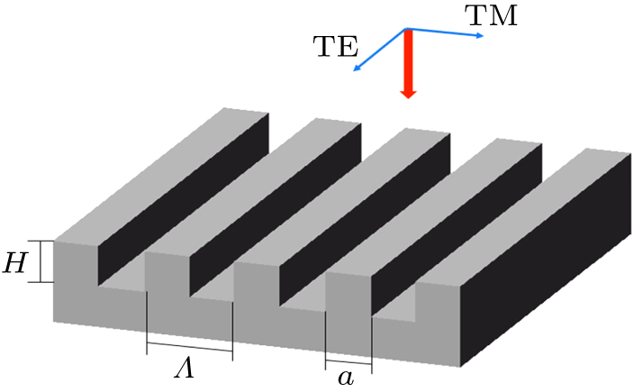
Fig. 1. Sub-wavelength grating structure. GaAs is the grating material, Λ is the period, H is the depth, a is the ridge width, and f = a /Λ is the duty cycle.
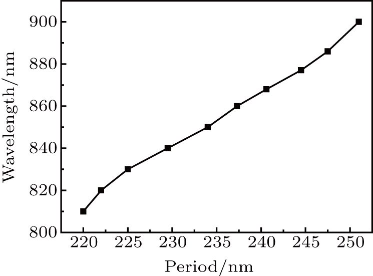
Fig. 2. The relationship between the period of sub-wavelength grating and wavelength when only zero-order diffraction light exists.
Fig. 3. The effect of ridge height and duty cycle to the transmittance of TE (a) and TM (b) polarization. When the duty ratio is 0.1–0.32 or 0.5–0.84, H is 80–135 nm. The two polarization modes can always maintain a significant difference in the effective index and transmittance.
Fig. 4. The schematic diagram of a trapezoidal sub-wavelength grating. Λ is the period, H is the ridge height, and θ is the inclination angle.
Fig. 5. The effect of θ on the transmittance and difference of polarization mode with the TE-type sub-wavelength grating (a) or the TM-type sub-wavelength grating (b).
Fig. 6. Schematic cross section of the tunable VCSEL with an internal-cavity sub-wavelength grating.
Fig. 7. The schematics of the tunable VCSELs with the SCC, EC, and ISWG structures, respectively.
Fig. 8. The relationship between air gap change and output wavelength.
Fig. 9. Electric field intensity distribution.
Fig. 10. The confinement factor (a) and the threshold gain (b) of the tunable VCSEL with SCC and ISWG structures, respectively.
Fig. 11. The relationship between θ top and wavelength of the three structures.
Fig. 12. The wavelength tuning range of the two polarization modes for the TE-type (a) and TM-type (b) tunable VCSEL, respectively, when θ is different.
Fig. 13. The relationship between threshold gain and different polarization modes for the TE-type tunable VCSEL (a) and the TM-type tunable VCSEL (b).
Fig. 14. At different injection currents, the OPSRs of the TE-type tunable VCSEL (a) and the TM-type tunable VCSEL (b).
Fig. 15. The material gain curve with different carrier concentrations (a) and temperatures (b).

Set citation alerts for the article
Please enter your email address
© Copyright 2018-2021 | Chinese Laser Press. All Rights Reserved 沪ICP备15018463号-20