
Cong Ma, Hao Chen, Xingwei Ye, Xiangchuan Wang, Shilong Pan. Ultra-high resolution microwave photonic radar with post-bandwidth synthesis[J]. Chinese Optics Letters, 2020, 18(7): 072501
- Chinese Optics Letters
- Vol. 18, Issue 7, 072501 (2020)
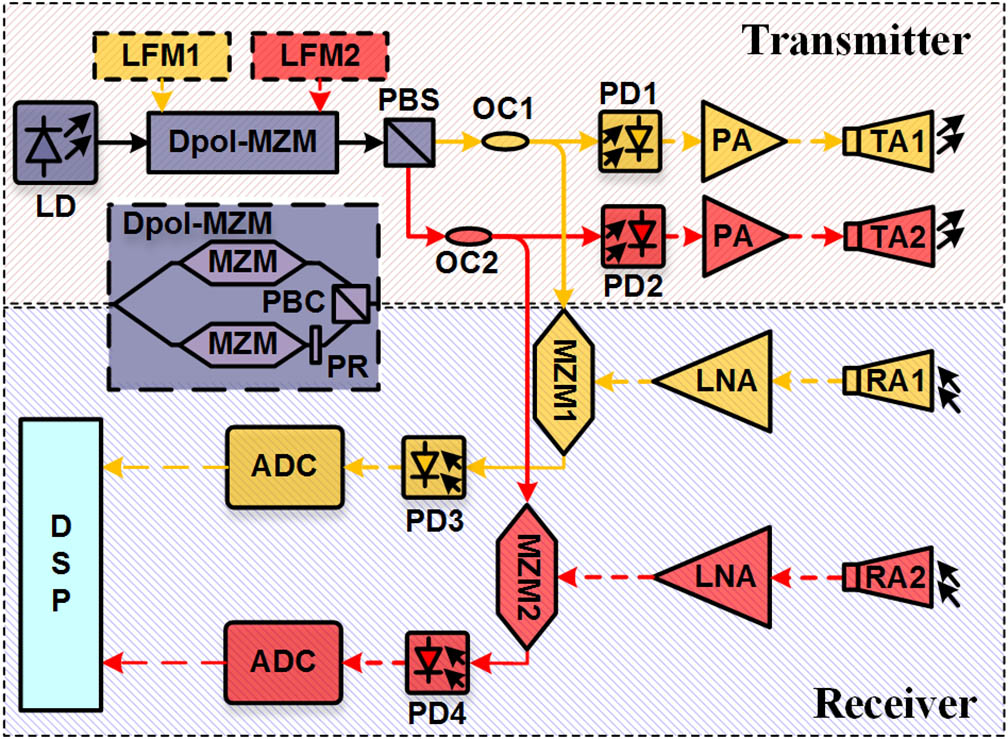
Fig. 1. Schematic diagram of the proposed microwave photonic radar. LD, laser diode; DPol-MZM, dual-polarization Mach–Zehnder modulator; MZM, Mach–Zehnder modulator; PR, polarization rotator; PBC, polarization beam combiner; PBS, polarization beam splitter; OC, optical coupler; PD, photodetector; PA, power amplifier; TA, transmitting antenna; RA, receiving antenna; LNA, low-noise amplifier. Solid line, optical fiber; dashed line, electrical cable. Yellow, channel X; red, channel Y.
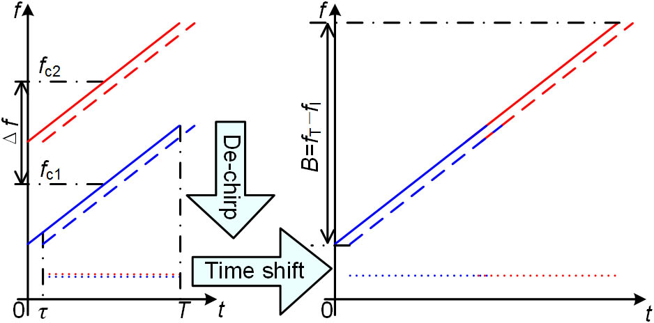
Fig. 2. The principle of the post-bandwidth synthesis. Solid line, the transmitted LFM signals; dashed line, the received LFM signals; dotted line, the de-chirped signals.
Fig. 3. Optical spectra of the polarized optical signals at (a) channel X and (b) channel Y.
Fig. 4. The frequency-time diagrams of the LFM signals generated in (a) channel X and (b) channel Y.
Fig. 5. Picture of the antennas and targets in the experiment. Inset, top-view of the targets.
Fig. 6. Spectra of the de-chirped signals generated in (a) channel X and (b) channel Y when two LFM signals with bandwidths of 2.1 GHz are transmitted. (c) Comparison between the spectra obtained by a real 4 GHz signal and the synthetic signal.
Fig. 7. (a) Comparison between the waveforms of the real and synthetic de-chirped signals. (b), (c), (d) Zoom-in views of the regions A, B, and C in (a).
Fig. 8. Spectra of the de-chirped signals generated at (a) channel X and (b) channel Y when two LFM signals with bandwidths of 8.4 GHz are transmitted. (c) The spectrum of the synthetic de-chirped signal. (a2), (b2), (c2) The zoom-in views of (a1), (b1), and (c1).

Set citation alerts for the article
Please enter your email address
© Copyright 2018-2021 | Chinese Laser Press. All Rights Reserved 沪ICP备15018463号-20