
Jiajie Teng, Chengyang Hu, Honghao Huang, Minghua Chen, Sigang Yang, Hongwei Chen. Single-shot 3D tracking based on polarization multiplexed Fourier-phase camera[J]. Photonics Research, 2021, 9(10): 1924
- Photonics Research
- Vol. 9, Issue 10, 1924 (2021)
Abstract
1. INTRODUCTION
Moving targets tracking in 3D space has found many applications in various fields, such as vehicle navigation, 3D reconstruction [1], and 3D motion estimation [2]. The most widely known image-free 3D sensor is LiDAR [3,4], which generally utilizes a laser as the active lighting source and high-bandwidth detector with complex data processing to achieve long-distance and high-speed 3D detection. However, due to the costly and complicated system architecture, it is hard to be widely utilized in normal 3D vision tasks. In contrast, image-based sensors or systems are with relatively low cost and common for a wider range of 3D visual applications, such as stereo vision [5,6] and monocular 3D systems [7], which allow the moving objects to track in different scales. Nevertheless, image-based systems often require a series of operations including camera pose estimation, multi-view calibration, feature extraction, and similarity matching, which increase the computational burden of the real-time 3D tracking.
With the advance of novel visional sensors, optoelectronics hybrid devices, and post-reconstruction algorithm, a serious of new camera architectures have emerged to tackle the challenging scenarios that are inaccessible to the traditional sensors. An event camera with high temporal resolution and high dynamic range provides a new data format with pixel-wise intensity changes asynchronously. This time-sparse event data reduces the power and bandwidth requirements and allows it to work in real-time 3D reconstruction for various vision applications [8,9]. For releasing the hardware requirement, a single-pixel detector is also applied to achieve a real-time image-free 3D tracking system [10]. Although this scheme faces trouble in the multi-objects tracking scenarios, it is still a low-cost and computation-efficient system. On the other hand, with the popularity of multi-dimensional encoded optoelectronic modulation devices, computational photography shows great potential in 3D reconstruction with single-shot stereo images [11–13], which is capable of cooperating with compressive sensing and adaptive reconstruction algorithms. Moreover, the lensless imaging system with a diffuser placed in front of the traditional sensor is demonstrated to achieve a single-shot 3D reconstruction in Refs. [14,15]. However, the effective resolution and computational overhead vary significantly with scene content and limit its practical application.
In this paper, we propose a four-dimensional (4D) information recording camera with multiplexed orthogonal polarization field-of-view (FoV), named polarization multiplexed Fourier-phase camera (PM-FPC). It is a novel camera framework, which is capable of reconstructing 4D data of moving objects in a single shot. The principle of PM-FPC is to perform pixel-wise optical coding on polarization multiplexed scenes to acquire the Fourier-phase maps of two orthogonal perspectives in one exposure. With the 8 bit grayscale quantized sinusoid modulation, the temporal resolution of the camera is increased to 256 times. Compared to the traditional image-based 3D stereo systems, it processes Fourier-phase transforming in the optical domain and has lower computational burden owing to the straightforward matching algorithm. Meanwhile, the image data volume and detection bandwidth get decreased due to the designed coding scheme with polarization multiplexing. Besides, it is able to plug in a standard camera system and adapt to various lighting environments with tunable exposure time. The experiment results with different 3D trajectories show its potential in real-time 3D motion estimation and recognition.
Sign up for Photonics Research TOC. Get the latest issue of Photonics Research delivered right to you!Sign up now
2. PRINCIPLES
A. Polarization Multiplexing and Demultiplexing
Polarization is a basic property of light, expressed as the vibration direction of the light-field. Here, we employ two orthogonal polarization states, polar-0° and polar-90°, to carry the duplet perspectives of the moving objects. A polarization beam splitter (PBS) is placed in the reverse direction to work as a combiner to generate the overlapping scene after the polarization multiplexing, which is shown in Fig. 1(b). Then, through the zooming lens, the overlapped scene is focused on the digital micromirror device (DMD), which temporally modulates each coding channel with four-phase-shifting sinusoid coding patterns to acquire the Fourier phase. Every coding channel is detected by the binning polarization pixels, which are mounted in front of the polarization charge-coupled device (CCD). Thus, the phase information () and polarization states (0°, 45°, 90°, 135°) can be acquired at the same time. Similar to the polarization extraction scheme in Ref. [13], with the known polarization array, it is able to reassemble the multiplexed scenes by simply extracting the polar-0° and polar-90° values and constructing two perspectives. The whole polarization multiplexing and demultiplexing process is depicted in Fig. 1. The extinction ratio of the PBS and the polarizer array in the camera will determine the orthogonal FoV’s crosstalk level in the measurements.
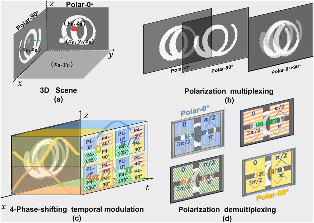
Figure 1.Polarization multiplexing and demultiplexing process. (a) The 3D coordinate synthesized by the two orthogonal 2D plane. (b) Overlapping scene after the polarization multiplexing. (c) The detection image with four-phase-shifting temporal modulation. (d) Polarization demultiplexing process.
B. Fourier-Phase Transforming
When an object is moving through the scene, each detection channel in the sensor will get a similar temporal pulse with a different rising edge. According to the brightness constancy of the objects, , the intensity of the voxel remains the same despite small changes of position and time period [16]. Thus, these temporal signals can be simply expressed as an impulse with spatial-variant time shifting. However, this information cannot be resolved in one exposure with a traditional camera. Herein, PM-FPC is designed to record this time-shift information through the optical coding method. With the principle of the discrete Fourier transform (DFT), a temporal signal can be represented by a series of discrete Fourier coefficients with different sampling frequencies. A shift in the time corresponds to the Fourier-phase shift in each encoded channel. To avoid phase unwrapping errors [17], we choose one period sinusoid pattern as the sampling frequency, which means only the first-order Fourier coefficients (1st DFT) in the optical coding process are used. The detailed time-encoded process in each channel is displayed in Fig. 2(a). On the sensor, binning pixels consist of one temporal coding channel named channel . With the pulse width modulation (PWM) mode of the DMD, four-phase-shifting sinusoid patterns () have temporally modulated on each coding channel. In a single-shot image of the sensor, a series of Fourier-phase number () is detected. As illustrated in Eq. (1), the Fourier-phase number is the integration of the Hadamard product between the sinusoid pattern and temporal signal of coding channel :
![]()
Figure 2.Fourier-phase transforming process. (a) Time-encoded process in coding channel
C. 3D Mapping and Tracking
The proposed system follows a parallel 3D mapping and tracking philosophy, where the main modules operate in the one-way fashion estimating the final 4D data (, , , ). A detailed overview of the flowchart is given in Fig. 3. Core modules of the system including Fourier-phase measuring, matching, and mapping processes are marked with dashed rectangles. The only input to the system is a single-shot 2D image of the PM-FPC. Through the measuring process, the Fourier-phase map of two orthogonal views is generated. For removing the phase interference caused by the environmental noise, it implements the mask extraction by setting the amplitude threshold, which is generally set to 1/10 of the average pixel intensity in the image. Besides, the initial phase of the exposure needs to be calibrated before the time-phase mapping process. The matching operation is applied between two orthogonal planes, the XOZ and YOZ planes. With the height-consistency calibration in the experiment, the moving target appears at the same height () of two orthogonal planes with its unique phase. Based on this, it can simply take any non-zero phase point P1(, ) on the XOZ plane as the reference, to traverse all the pixels with the same height in the YOZ plane to find the correspondence point P2(, ), which has the smallest phase difference with P1. After this straightforward matching process, the 3D coordinates (, , ) of the corresponding point are determined. Then, with the time-phase mapping relationship shown in Eq. (4), the time information of the object moving through the scenes can be calculated out through the precise phase measurement. Relying on the time-spatial consistency in the XOZ and YOZ plane, the 3D coordinates and time information of the object are synthesized out, which consist of the 4D datasets (, , , ) as the final output.
![]()
Figure 3.Proposed system flowchart.
3. EXPERIMENT AND RESULTS
The schematic diagram of the experiment is shown in Fig. 4. Light from two orthogonal views is reflected by mirrors M1 and M2 and filtered by the PBS. Respectively, the duplet views get tagged with two polarization states (polar-0° and polar-90°) and combined to be a view-overlapped scene, which is further imaged and projected on a DMD (ViALUX V-9500) through the imaging lens. The DMD is employed to implement the pixel-wise temporal modulation on each coding channel [19], which is modulated by the parallel four-phase-shifting sinusoidal pattern (). Each phase-encoded channel is composed of sub-pixels corresponding to four polarizations (0°, 45°, 90°, 135°). The polarization camera (FLIR BPS-PGE-51S5P-C) applied in the system has pixels mounted with different polarizers, and the pixel size is 3.45 μm. The DMD has a micro mirror, whose pixel size is 7.6 μm. Through a strict optical calibration (Appendix B), which creates a suitable FoV () with pixel-by-pixel correspondence (one micro-mirror corresponding to polar pixels), the Fourier-phase map of the duplet view is measured, respectively. After the mask extraction and phase calibration steps, the matching process is applied between the XOZ and YOZ phase map. Then, the 3D position and time information of the object are derived by the time-phase mapping results. In the experiment, a motorized stage (Zolix LA100-60-ST) is utilized to build the horizontal linear movement of the target. When it comes to the circle motion scenes, an optical chopper (Thorlabs MC200B) with tunable frequency is implemented to work as a rotating stage. For a more complex motion scene, the vertical rotation and horizontal linear movement are combined to produce a spiral motion. The exposure time with each trajectory is different depending on the illumination and lighting conditions. Based on the Fourier-phase coding scheme, one coding channel corresponds to pixels on the polarization camera, so the maximum spatial resolution of the reconstructed 3D space is 1/4 of camera resolution (). However, for better phase measurement results, we utilize binning pixels on the camera to perform as one coding channel and choose an illuminous LED as the moving object. In the first place, we test a dynamic scene with one object, including linear and circular motion, which is depicted in Fig. 5(a). The diameter of the objects is 5 mm, and the horizontal movement speed is 20 mm/s. In the one-line test, the exposure time is set at 2 s with 100 pixel length trajectory in the picture, which is consistent with the actual FoV and zoom ratio (0.645). In the circular motion, the period of the object motion is 320 ms, which is accordant to the rotation frequency (3.1 Hz) of the chopper. The reconstructed 3D position of these scenes is marked with the solid sphere with the changing color indicating the time information. The effective temporal resolution of the reconstruction is dependent on the exposure time and gray quantization bit number of the DMD, which is discussed in the Appendix C. Here, with the 8 bit grayscale DMD and 200 ms exposure time, the equivalent temporal resolution is 1280 fps (; fps, frames per second). Then, an object is added in the scene, and the results of two objects 3D tracking are shown in Fig. 5(b). In the multi-target tracking, the spatial-temporal restriction is utilized, which is the Euclidean distance [20] between the previous phase point and the current one. Based on the distance restriction, the multiple targets with different motion can also be distinguished in a single shot.
![]()
Figure 4.Schematic diagram of the polarization multiplexed Fourier-phase camera.
![]()
Figure 5.(a) One object motion. (b) Two objects motion. (c) Rotation. (d) Handwriting heart (see
Furthermore, the object spiral motion with different exposure time (200 ms, 400 ms, 600 ms) is recorded and reconstructed, where the spiral forward speed is also 20 mm/s, and the rotation period is 160 ms. As shown in Fig. 5(c), these 3D tracking results all fit well to the real 3D trajectory marked with the gray sphere in the time 3D maps. To further verify the system potential in the 3D motion recognition, we also tested one handwriting trajectory with the heart shape, the results are displayed in Fig. 5(d). It is noted that in the complicated motion scene, the trajectory crossing area is unpreventable with the increasing exposure, which leads to inaccurate 4D reconstruction and poor matching results. To solve this problem, phase loss function and motion estimation are added to mitigate the effect of phase error. Some phase optimization in the crossing area is discussed in Appendix F, such as the K-means clustering [19], cubic spline interpolation [21], and Kalman filter [22]. Owing to these optimizations, a dynamic 3D handwriting trajectory of the heart and its matching process are displayed in
4. CONCLUSION
In conclusion, we proposed a single-shot 3D tracking system based on a novel camera architecture and a new image format: Fourier-phase map. The principle of the system is to acquire the time-phase shifting of the target in two orthogonal views with different polarization states. Only one 2D image with motion trajectory is needed to reconstruct the 4D data (, , , ) of the target. Owing to the polarization multiplexing and optical coding method, the detection bandwidth gets significantly decreased, which makes it work well in a low-cost polarization camera with efficient reconstruction algorithms. Meanwhile, the Fourier-phase transforming in the optical domain reduces the computational overhead from the data acquisition and quantization in the calculation. Compared with the traditional tracking system based on the frame difference method, simple algorithms, such as the phase-matching and time-phase mapping processes, relevantly mitigate the cost of the computation. In the experiment, the effective frame rate of the camera is achieved at 1280 fps under the exposure time of 200 ms, which breaks the exposure constraint of a traditional camera with the preset temporal resolution. With the long-exposure detection scheme, PM-FPC has higher SNR than normal high-speed cameras, providing it with the ability to capture the dynamic objects under low-light 3D scenes. In addition, owing to the pixel-mounted polarizer array, PM-FPC can filter the inevitable glare and specular interference, which is a great challenge to a traditional camera. Besides, to achieve more efficient and accurate phase-to-depth mapping, the universal stereo vision system is considered to replace the orthogonal view system. For the wider application in the 3D motion estimation, the phase prediction process is added on the trajectory crossing area. Furthermore, it is expected to realize a real-time 3D motion prediction and multi-target detection system with the development of the neural network under new data types [23,24].
APPENDIX A: QUANTITATIVE ANALYSIS ON THE PERFORMANCE OF PM-FPC
To validate the proposed scheme of the PM-FPC, a numerical simulation is designed before the experiment. There are two simulated 3D scenes: the one is a sphere with a radius of 10 pixels moving along a spiral path, and the other is a pair of parallel spheres moving through the scenes, which verified its ability of multi-objects 3D tracking. As shown in Fig.
![]()
Figure 6.Simulation results.
APPENDIX B: OPTICAL CALIBRATION
Similar to an optical coding camera system, the plug-in optical devices need to be carefully calibrated before the Fourier-phase measurement. First, the imaging lens and the relay lens in the system are both designed for clear imaging effects with suitable FoV. It is important to record the whole object trajectory during the exposure time. Another key parameter in PM-FPC is the pixel-to-pixel correspondence between the DMD and the polarization sensor. There are two common errors in the pixel-to-pixel calibration: the mismatch and the misalignment, which are difficult to observe through the imaging. Fortunately, the sensor and DMD can be regarded as two spatial gratings, so the Moire fringe operation illustrated in Ref. [
APPENDIX C: EFFECTIVE TEMPORAL RESOLUTION
As the object moves in the scene, the temporal signals at different pixel channels are of different time-pulse positions, leading to coincidence phase shift in the 1st DFT coefficient. Here, the accuracy of the Fourier-phase measurement is the temporal resolution of the 3D tracking in PM-FPC. The phase measurement accuracy is determined by the DMD quantization bits for temporal grayscale coding and the exposure time () of the image sensor. The temporal resolution is illustrated as the following equation:
APPENDIX D: SNR IN THE PM-FPC
SNR is utilized to describe the quality of the measurement, which is particularly important in applications requiring a precise object tracking system. More specifically, it is the ratio of the measured signal to the overall measured noise (frame-to-frame) during the CCD’s exposure time. Here, we only consider the overall camera SNR under global exposure, not the pixel-level SNR, which is usually variable with the objects’ motion. There are three primary sources of noise in a camera system: photo noise, dark noise, and read noise [
APPENDIX E: DATA VOLUME
Assuming this 3D tracking task is finished by the stereo cameras with frames and pixels in each frame, its data volume is bytes (1 byte for one pixel channel). PM-FPC processes the same resolution 3D tracking through a polarization camera with a single-shot image. In the optical coding process, each phase-shifting sinusoidal pattern corresponds to polarization filters on the sensor. -step phase-shifting patterns are utilized for more precise phase measurement. It means that binning pixels consist of one coding channel to measure the Fourier phase of the signal. With the ideal correspondence between the DMD and the image sensor, the minimum spatial-encoded pixel size is . Here, we propose a ratio value to represent the data volume comparison between the stereo cameras and PM-FPC, and the equation is listed as follows:
APPENDIX F: PHASE OPTIMIZATION IN THE CROSSING AREA
As mentioned above, the principle of PM-FPC is the time-shift impulse leading to the pixel-wise phase shift in the Fourier domain during the exposure time. Therefore, when it has two impulses occurring in the same pixel, the phase measuring scheme will lose its precision in this area, which is also called phase entanglement. This effect directly leads to phase mismatching and time information loss. For wider applications, phase estimation and prediction are needed to solve this problem through the spatio-temporal continuity with the object motion. Assuming that the phase change of the moving target is continuous in the phase maps, the real phase information in the crossing area can be estimated among the neighborhood phase values. Here, we choose the -means clustering [
![]()
Figure 7.Phase optimization in the crossing area.
References
[1] D. A. Forsyth, J. Ponce. Computer Vision: A Modern Approach(2012).
[2] D. Pathak, R. Girshick, P. Dollár, T. Darrell, B. Hariharan. Learning features by watching objects move. Proceedings of the IEEE Conference on Computer Vision and Pattern Recognition, 2701-2710(2017).
[3] S.-T. Park, J. G. Lee. Improved Kalman filter design for three-dimensional radar tracking. IEEE Trans. Aerosp. Electron. Syst., 37, 727-739(2001).
[4] A. Chaikovsky, Y. O. Grudo, Y. A. Karol, A. Y. Lopatsin, L. Chaikovskaya, S. Denisov, F. Osipenko, A. Slesar, M. Korol, Y. S. Balin, S. V. Samoilova. Regularizing algorithm and processing software for Raman lidar-sensing data. J. Appl. Spectrosc., 82, 779-787(2015).
[5] E. Seemann, K. Nickel, R. Stiefelhagen. Head pose estimation using stereo vision for human-robot interaction. 6th IEEE International Conference on Automatic Face and Gesture Recognition, 626-631(2004).
[6] R. Munoz-Salinas, E. Aguirre, M. Garca-Silvente. People detection and tracking using stereo vision and color. Image Vis. Comput., 25, 995-1007(2007).
[7] A. Mauri, R. Khemmar, B. Decoux, N. Ragot, R. Rossi, R. Trabelsi, R. Boutteau, J.-Y. Ertaud, X. Savatier. Deep learning for real-time 3D multi-object detection, localisation, and tracking: application to smart mobility. Sensors, 20, 532(2020).
[8] Y. Zhou, G. Gallego, H. Rebecq, L. Kneip, H. Li, D. Scaramuzza. Semi-dense 3D reconstruction with a stereo event camera. Proceedings of the European Conference on Computer Vision (ECCV), 235-251(2018).
[9] H. Rebecq, G. Gallego, E. Mueggler, D. Scaramuzza. EMVS: event-based multi-view stereo—3D reconstruction with an event camera in real-time. Int. J. Comput. Vis., 126, 1394-1414(2018).
[10] Q. Deng, Z. Zhang, J. Zhong. Image-free real-time 3-D tracking of a fast-moving object using dual-pixel detection. Opt. Lett., 45, 4734-4737(2020).
[11] Y. Sun, X. Yuan, S. Pang. Compressive high-speed stereo imaging. Opt. Express, 25, 18182-18190(2017).
[12] Z. Zhang, S. Zhang. One-shot 3D shape and color measurement using composite RGB fringe projection and optimum three-frequency selection. Proc. SPIE, 7511, 751103(2009).
[13] M. Qiao, X. Liu, X. Yuan. Snapshot spatial–temporal compressive imaging. Opt. Lett., 45, 1659-1662(2020).
[14] N. Antipa, G. Kuo, R. Heckel, B. Mildenhall, E. Bostan, R. Ng, L. Waller. Diffusercam: lensless single-exposure 3D imaging. Optica, 5, 1-9(2018).
[15] X. Feng, L. Gao. Ultrafast light field tomography for snapshot transient and non-line-of-sight imaging. Nat. Commun., 12, 2179(2021).
[16] T. Yamazato, M. Kinoshita, S. Arai, E. Souke, T. Yendo, T. Fujii, K. Kamakura, H. Okada. Vehicle motion and pixel illumination modeling for image sensor based visible light communication. IEEE J. Sel. Areas Commun., 33, 1793-1805(2015).
[17] C. Zhang, H. Zhao, X. Gao, Z. Zhang, J. Xi. Phase unwrapping error correction based on phase edge detection and classification. Opt. Lasers Eng., 137, 106389(2021).
[18] H. Huang, C. Hu, S. Yang, M. Chen, H. Chen. Temporal ghost imaging by means of Fourier spectrum acquisition. IEEE Photon. J., 12, 6803012(2020).
[19] A. Likas, N. Vlassis, J. J. Verbeek. The global k-means clustering algorithm. Pattern Recognit., 36, 451-461(2003).
[20] T. Saito, J. I. Toriwaki. New algorithms for euclidean distance transformation of an n-dimensional digitized picture with applications. Pattern Recognit., 27, 1551-1565(1994).
[21] S. McKinley, M. Levine. Cubic spline interpolation. Coll. Redwoods, 45, 1049-1060(1998).
[22] E. A. Wan, R. Van Der Merwe. The unscented Kalman filter for nonlinear estimation. Proceedings of the IEEE 2000 Adaptive Systems for Signal Processing, Communications, and Control Symposium, 153-158(2000).
[23] C. Hu, H. Huang, M. Chen, S. Yang, H. Chen. Fouriercam: a camera for video spectrum acquisition in a single shot. Photon. Res., 9, 701-713(2021).
[24] C. Hu, H. Huang, M. Chen, S. Yang, H. Chen. Video object detection from one single image through opto-electronic neural network. APL Photon., 6, 046104(2021).
[25] S. Ri, M. Fujigaki, T. Matui, Y. Morimoto. Accurate pixel-to-pixel correspondence adjustment in a digital micromirror device camera by using the phase-shifting Moiré method. Appl. Opt., 45, 6940-6946(2006).
[26] O.-C. M. Gain. On-Chip Multiplication Gain(2002).
[27] K. Krishna, M. N. Murty. Genetic k-means algorithm. IEEE Trans. Syst. Man Cybernet. B, 29, 433-439(1999).

Set citation alerts for the article
Please enter your email address
© Copyright 2018-2021 | Chinese Laser Press. All Rights Reserved 沪ICP备15018463号-20