
Xi-Feng Cao, Hui Liu, Da-Ren Yu. Research of influence of the additional electrode on Hall thruster plume by particle-in-cell simulation[J]. Chinese Physics B, 2020, 29(9):
- Chinese Physics B
- Vol. 29, Issue 9, (2020)
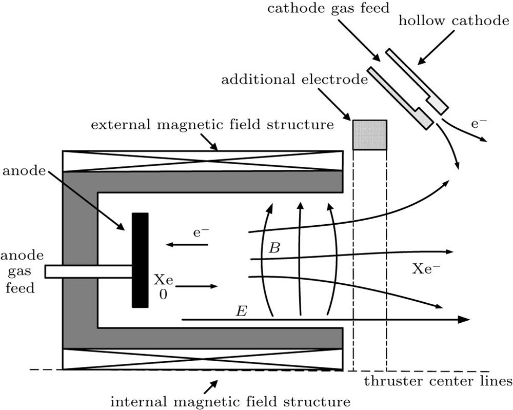
Fig. 1. The structure diagram of Hall thruster.
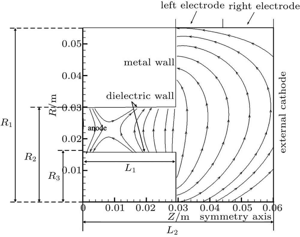
Fig. 2. Computational domain and boundary.
Fig. 3. Two-dimensional distribution of potential (initial case).
Fig. 4. Two-dimensional distribution of ion number density (initial case).
Fig. 5. The distribution of potential along the central axis of the channel.
Fig. 6. The distribution of potential in the plume under the three conditions: (a) initial, (b) left 30 V, and (c) right 30 V.
Fig. 7. The distribution of ion radial velocity at the upper boundary of the plume region under the seven conditions.
Fig. 8. Ion flux distribution at the upper boundary of plume region.
Fig. 9. The ratio of the total radial ion flux at different radial positions, based on the total radial ion flux at R = 0.03 m.
Fig. 10. Ion flux on the outer magnetic pole under the seven conditions. The range of outer magnetic pole is Z = 0.029 m–0.055 m.
|
Table 1. The area parameters in calculations.
|
Table 2. The half plume divergence angle under the seven conditions.
|
Table 3. Statistics of total ion deposition on the outer magnetic pole.


Set citation alerts for the article
Please enter your email address

© Copyright 2018-2021 | Chinese Laser Press. All Rights Reserved 沪ICP备15018463号-20