• Chinese Journal of Lasers
  • Vol. 51, Issue 4, 0402104 (2024)
Weizhe Du, Xuting Huang, Min Zheng, Rongshi Xiao, and Ting Huang*
Author Affiliations
  • Intelligent Photon Manufacturing Research Center, Faculty of Materials and Manufacturing, Beijing University of Technology, Beijing 100124, China
  • show less
    DOI: 10.3788/CJL231393 Cite this Article Set citation alerts
    Weizhe Du, Xuting Huang, Min Zheng, Rongshi Xiao, Ting Huang. Research Progress in Laser Micro‑welding of Metal Materials (Invited)[J]. Chinese Journal of Lasers, 2024, 51(4): 0402104 Copy Citation Text show less
    Structure diagram of this paper
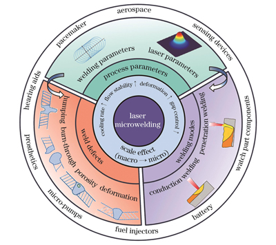
    Fig. 1. Structure diagram of this paper
    Characteristics of laser micro-welding. (a) Heat transfer[25]; (b) melt pool flow[18]; (c) deformation[26]; (d) gap sensitivity[13]
    Fig. 2. Characteristics of laser micro-welding. (a) Heat transfer[25]; (b) melt pool flow[18]; (c) deformation[26]; (d) gap sensitivity[13]
    Schematics of laser micro-welding modes. (a) Heat conduction welding; (b) deep penetration welding
    Fig. 3. Schematics of laser micro-welding modes. (a) Heat conduction welding; (b) deep penetration welding
    Study results of unstable transition zones in laser micro-welding. (a) Judging from width of weld, unstable transition zone is caused by alternating occurrence of heat conduction welding and deep penetration welding[23]; (b) combination of welding plume and weld width proves that unstable transition zone is caused by instability of deep penetration welding [31]
    Fig. 4. Study results of unstable transition zones in laser micro-welding. (a) Judging from width of weld, unstable transition zone is caused by alternating occurrence of heat conduction welding and deep penetration welding[23]; (b) combination of welding plume and weld width proves that unstable transition zone is caused by instability of deep penetration welding [31]
    Effect of laser micro-welding mode on microstructure of weld[31]. (a) Cross section and phase composition of heat conduction welding joint of stainless steel; (b) cross section and phase composition of deep penetration welding joint of stainless steel
    Fig. 5. Effect of laser micro-welding mode on microstructure of weld[31]. (a) Cross section and phase composition of heat conduction welding joint of stainless steel; (b) cross section and phase composition of deep penetration welding joint of stainless steel
    Effects of lasers on laser micro-welding. (a) Surface morphologies of copper welds welded by green laser and near-infrared laser[37]; (b) surface and cross-section morphologies of welds in aluminum/copper dissimilar metal lap welding by ARM laser[39]; (c) surface and cross-section morphologies of welds in aluminum/stainless steel butt welding by femtosecond laser[40]
    Fig. 6. Effects of lasers on laser micro-welding. (a) Surface morphologies of copper welds welded by green laser and near-infrared laser[37]; (b) surface and cross-section morphologies of welds in aluminum/copper dissimilar metal lap welding by ARM laser[39]; (c) surface and cross-section morphologies of welds in aluminum/stainless steel butt welding by femtosecond laser[40]
    Typical defects of laser micro-welding. (a) Incomplete penetration; (b) burn-through; (c) undercut; (d) spatter; (e) pore; (f) crack; (g) humping; (h) deformation
    Fig. 7. Typical defects of laser micro-welding. (a) Incomplete penetration; (b) burn-through; (c) undercut; (d) spatter; (e) pore; (f) crack; (g) humping; (h) deformation
    Humping in welding. (a) Surface and cross-section morphologies of humping; (b) formation mechanism of humping
    Fig. 8. Humping in welding. (a) Surface and cross-section morphologies of humping; (b) formation mechanism of humping
    Surface morphology and cross-section morphology of laser welded metal foil stacks. (a) Green laser welding of copper foil[36]; (b) blue laser welding of copper foil[35]
    Fig. 9. Surface morphology and cross-section morphology of laser welded metal foil stacks. (a) Green laser welding of copper foil[36]; (b) blue laser welding of copper foil[35]
    Effects of laser power and beam diameter on weld formation. (a) Cross-section morphologies of welds at different powers when spot diameters are 34.8 μm and 17.4 μm, respectively[62]; (b) surface morphologies of welds at different powers and speeds when spot diameters are 200 μm and 375 μm , respectively[63]
    Fig. 10. Effects of laser power and beam diameter on weld formation. (a) Cross-section morphologies of welds at different powers when spot diameters are 34.8 μm and 17.4 μm, respectively[62]; (b) surface morphologies of welds at different powers and speeds when spot diameters are 200 μm and 375 μm , respectively[63]
    Effects of oscillation scanning on weld formation and molten pool. (a) Scanning images of cross sections of aluminum/copper dissimilar metal welds by energy disperse spectrometer (EDS)[68]; (b) dynamic behaviors of molten pools during linear scanning welding and oscillating welding captured by high-speed photography[70]
    Fig. 11. Effects of oscillation scanning on weld formation and molten pool. (a) Scanning images of cross sections of aluminum/copper dissimilar metal welds by energy disperse spectrometer (EDS)[68]; (b) dynamic behaviors of molten pools during linear scanning welding and oscillating welding captured by high-speed photography[70]
    Application of laser micro-welding of metal materials. (a) Pressure sensor[71]; (b) bipolar plate for fuel cells[72]; (c) blades for aerospace engines; (d) electronic component pins and copper printed circuit board[73]; (e) tantalum satellite collimator[76]; (f) cardiac pacemaker[74]; (g)‒(i) lithium ion battery tabs[79]
    Fig. 12. Application of laser micro-welding of metal materials. (a) Pressure sensor[71]; (b) bipolar plate for fuel cells[72]; (c) blades for aerospace engines; (d) electronic component pins and copper printed circuit board[73]; (e) tantalum satellite collimator[76]; (f) cardiac pacemaker[74]; (g)‒(i) lithium ion battery tabs[79]
    TypeWavelength /nm

    Spot

    size /μm

    Pulse

    width /ms

    Pulse frequence /HzWelding speed /(mm/s)MaterialThickness /μm
    Semiconductor blue laser3545058Cu10
    Disk laser36515115012.5/10.0/5.0Cu10
    Disk laser3751548.516.7‒ 266.7Cu250
    Disk laser385151471.8‒3.2139.8‒210.34-11Cu10
    ARM laser39107070/180200/500Al/Cu400+400
    Femtosecond laser41800253.5×10-11100025/125Ag/Cu25+125
    Pulsed Nd∶YAG4210642001.5‒305.012‒201.4‒5.4316L stainless steel100+100
    Pulsed Nd:YAG431064200439316L stainless steel100+3000
    Pulsed Nd:YAG4410642001.5‒3.514-183.4316L stainless steel100+100
    Pulsed fiber laser4550020316L stainless steel70
    CW fiber laser46109017.5/35.0500‒2000304 stainless steel50
    CW fiber laser471090351000304 stainless steel50/20
    CW fiber laser48107050‒300Cu300+300
    CW fiber laser49107030200‒1000Al/Cu200+200
    CW fiber laser50107068/175150‒250Al/Cu450+300
    CW fiber laser5110702450Al/Cu500+500
    Table 1. Typical light sources and research results of laser micro-welding
    Weizhe Du, Xuting Huang, Min Zheng, Rongshi Xiao, Ting Huang. Research Progress in Laser Micro‑welding of Metal Materials (Invited)[J]. Chinese Journal of Lasers, 2024, 51(4): 0402104
    Download Citation