- Chinese Journal of Lasers
- Vol. 45, Issue 11, 1106005 (2018)
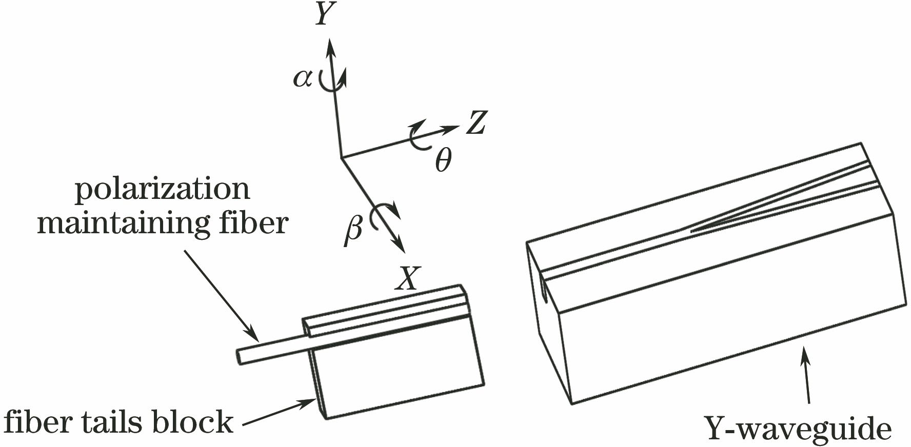
Fig. 1. Alignment coupling model of fiber and input end of Y-waveguide
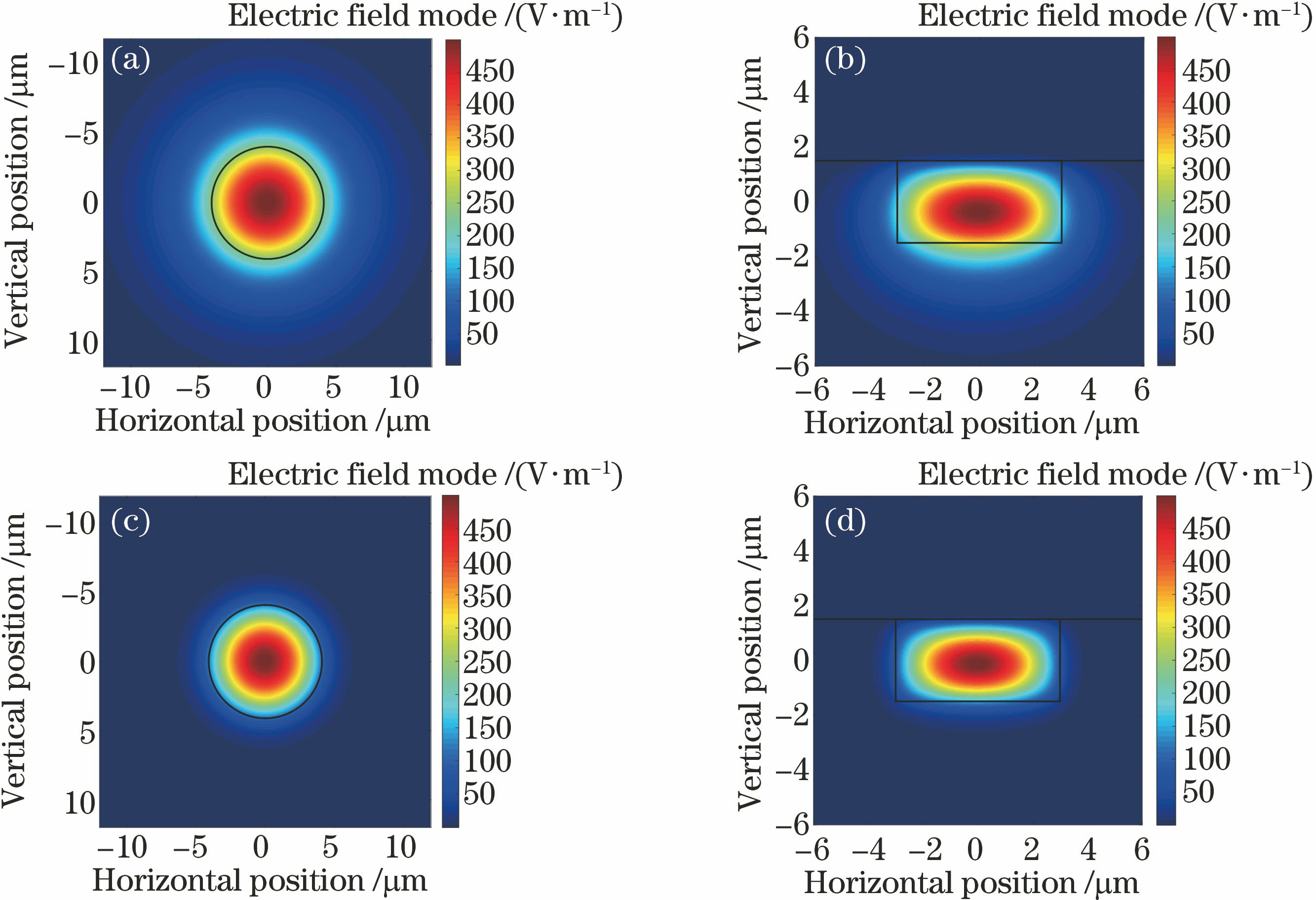
Fig. 2. Simulation diagrams of mode field. (a) Fiber, 1550 nm; (b) waveguide, 1550 nm; (c) fiber, 650 nm; (d) waveguide, 650 nm
Fig. 3. Schematic of experimental platform of alignment coupling between fiber and waveguide
Fig. 4. Experimental images. (a) Side image of coupling point; (b) output image of Y-waveguide; (c) output image after adjusting light intensity
Fig. 5. Distributions of red channel values of output point. (a) Horizontal position; (b) vertical position
Fig. 6. Relation curves between coupling loss and transverse misalignment. (a) Transverse misalignment X; (b) transverse misalignment Y
Fig. 7. Relation curves between coupling loss and vertical spacing Z
Fig. 8. Alignment coupling model of fiber and Y-waveguide under deflection angle α
Fig. 9. Relation curves between coupling loss and angle deflection. (a) Deflection angle α; (b) pitch angle β
Fig. 10. Relation curves between coupling loss and angle deflection. (a) Deflection angle α; (b) pitch angle β; (c) deflection angle α with L=100, 200, 500, 1000, 1500, 2000 μm


Set citation alerts for the article
Please enter your email address
© Copyright 2018-2021 | Chinese Laser Press. All Rights Reserved 沪ICP备15018463号-20