
Suhas Bhandarkar, Nick Teslich, Ben Haid, Evan Mapoles. Importance of limiting hohlraum leaks at cryogenic temperatures on NIF targets[J]. High Power Laser Science and Engineering, 2017, 5(3): 03000e19
- High Power Laser Science and Engineering
- Vol. 5, Issue 3, 03000e19 (2017)
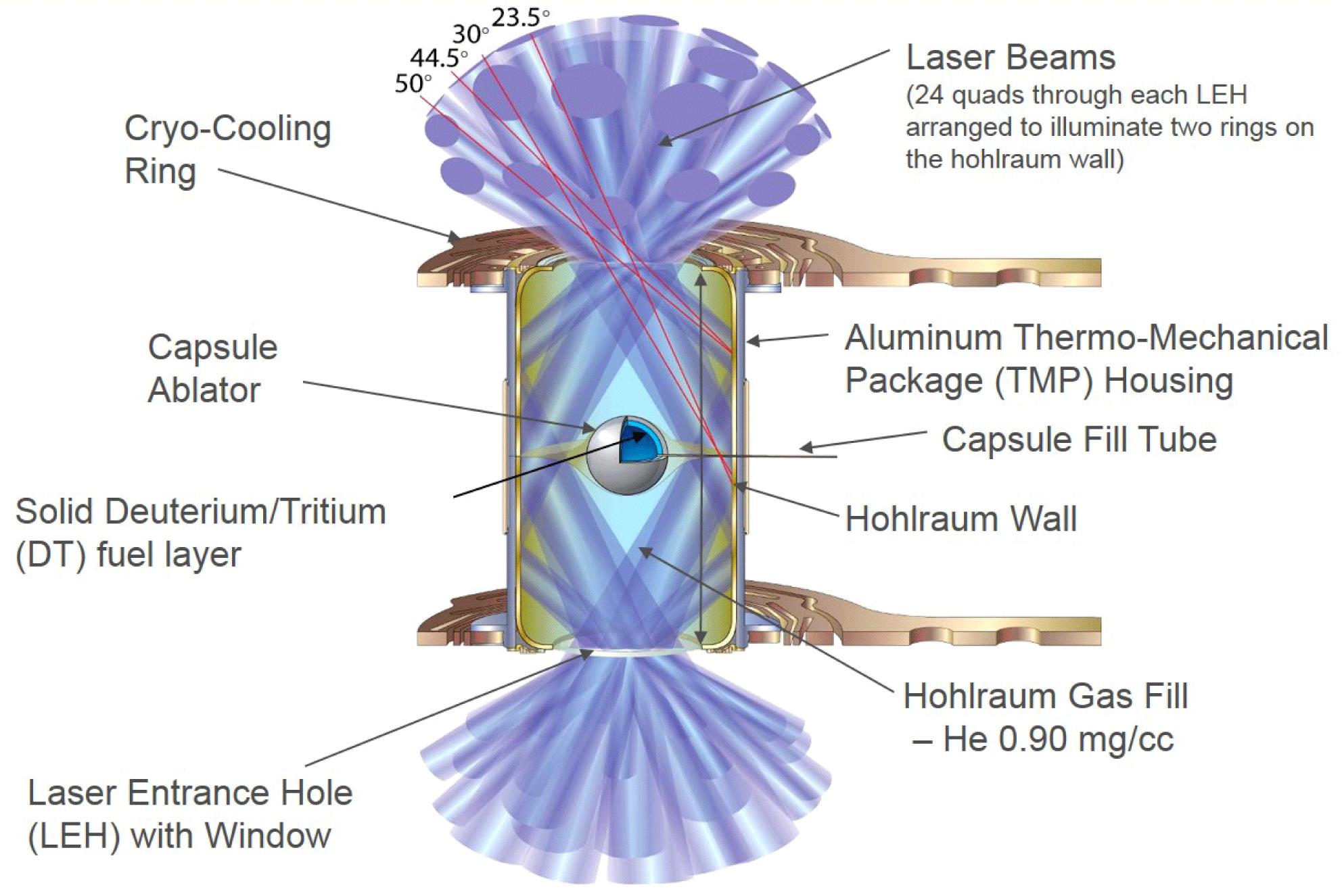
Fig. 1. Schematic of the core part of an ICF target showing the hohlraum, capsule ablator and the DT ice. The laser beams impinge on the hohlraum walls and provide the energy for the fusion reaction.
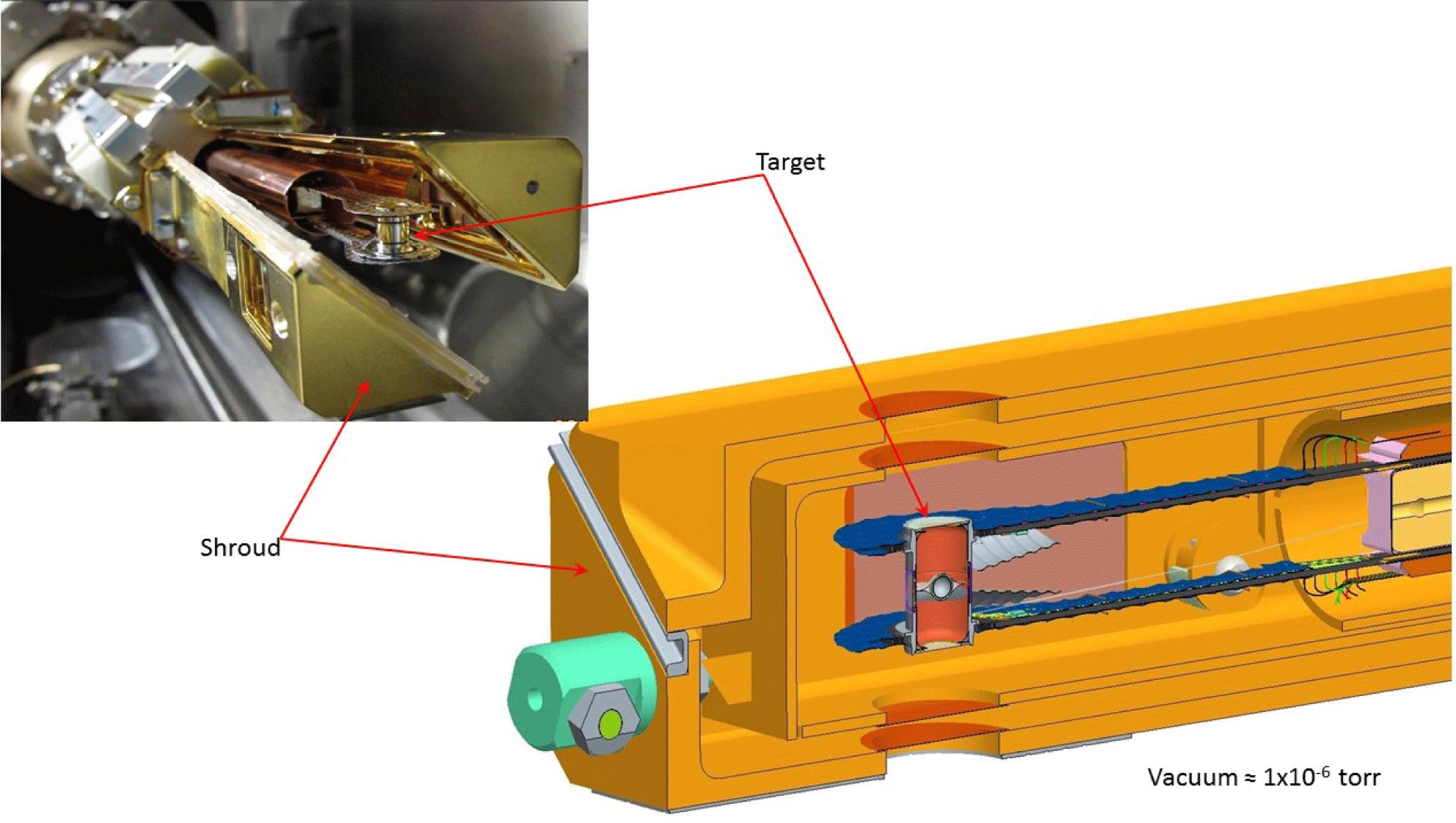
Fig. 2. Sketch and photograph (upper left) showing the clamshell shroud that shields the target from the ambient outside during the layering process.
Fig. 3. Target is a micro-assembly of many components, some of which are shown above. There are several temperature sensors and heaters, though only one set is shown above.
Fig. 4. Matching the model and the data using a $25~\unicode[STIX]{x03BC}\text{m}$ diameter orifice.
Fig. 5. Relationship between an orifice diameter and the corresponding flow rate at 18 K and 450 torr upstream pressure.
Fig. 6. Results from the cryogenic proofing of the hohlraum at cryogenic temperature. The solid blue line is the supply line pressure while the dotted blue line is that of the return line. The red dots are the corresponding leak rate. Both lines are open to the hohlraum after 1000 s.
Fig. 7. Schematic of the TMP window washer to Al TMP bonding design. The picture on the right is an image of the typical LEH bonding operation.
Fig. 8. SEM images of features seen in the LEH to TMP bondline of a failed target. The red circle highlights the arc where dark bands, like the one seen in the lower left, were seen. These bands were seen to be linear holes in the bondline (image on the right).
Fig. 9. SEM image of the FIB etched section showing the internal cross-section of the region under the band seen in Figure 8 .
Fig. 10. Schematic of the hypothesis used to account for the FIB-SEM results.
Fig. 11. Plot showing the cumulative failures as a function of number of the targets built, representing a snapshot in time in target production. Note that the first instance of failure was around target 25. The installation of the fixture for vertical curing was implemented at target # 119, after which the failures stopped.

Set citation alerts for the article
Please enter your email address
© Copyright 2018-2021 | Chinese Laser Press. All Rights Reserved 沪ICP备15018463号-20