Beijing Engineering Research Center for Mixed Reality and Advanced Display, School of Optoelectronics, Beijing Institute of Technology, Beijing 100081, China
Feng Chen, Yue Liu, Tao Yang. Color correction for tiled projection with irregularly shaped, overlapping region[J]. Chinese Optics Letters, 2015, 13(9): 093301
Copy Citation Text
In this Letter, a new, constrained color-matching algorithm that removes the color variations is presented, in which all the color gamut of the projectors is mapped into a common gamut that can be produced by all the devices in the system. The smoothness constraints on the difference between two adjacent pixels are taken into account to calculate the luminance attenuation map of each pixel in the overlapping region to achieve luminance seamlessness. The experimental results demonstrate the validity and superiority of this correction algorithm.
With the development of projectors and computer graphics, it is now much easier to generate large-scale images with video projectors[1,2]. Two aspects of calibrations, geometric registration and color correction, have been introduced to make sure that the image from the multi-projector system is seamless[3]. Most multi-projector displays are typically designed with regular configurations of projectors and for regular display surfaces[4]. If the surfaces to be projected are not planar, the shape of the overlapping region across the adjacent projectors will be irregular. Although a geometric map can be acquired through such calibration techniques as gray-coded structured light, the spatial variation in color remains the obstacle towards achieving seamless, tiled, multi-projector displays[5,6] that possess significant spatial variations in color due to variations in the chromaticity across the projectors, the vignetting effect of each projector, as well as the overlapping region across adjacent projectors[7].
Various techniques have been developed to eliminate the color variations of the multi-projector system. The existing ways focus on systems in which the shape of the overlapping region between the adjacent projectors is regular. Color is defined by both luminance and chrominance. Majumder and Stevens proved that most current tiled displays composed of projectors of the same manufacturer model show large spatial variations in luminance, while the chrominance is almost spatially constant[8,9]. Human eyes are also at least an order of magnitude more sensitive to a variation of luminance than to that of chrominance[10]. Thus, perceptually, the luminance variation is the most significant contributor to the color variation. In multi-projector displays, the variations in color can be classified into three different categories: intra-projector variation, inter-projector variation, and overlap variation[9]. Stone et al. used a point light measuring instrument such as a spectroradiometer to measure the color gamut for each projector at one spatial location[11]. Raskar et al. use blending and feathering techniques to address the problems of overlapping regions and try to smooth color transitions across these regions[12]. Sajadi et al. proposed a gamut morphing scheme to correct the color variations across multi-projector displays, which helps the achievement of reasonable seamlessness when the shape of the overlapping region is rectangular[13]. All the methods mentioned above require the system to have a regular-shaped overlap or identical color gamut; they will not perform well if the condition is not fulfilled. In this Letter, a new, constrained color-matching algorithm that eliminates the color variations is presented. Two stages of correction, gamut matching and constraint luminance smoothing, will be respectively adopted to deal with the chrominance and luminance variations of the system.
In the first stage, the gamut of all the projectors will be mapped into a common color gamut so as to remove the chrominance variation.
Sign up for Chinese Optics Letters TOC. Get the latest issue of Chinese Optics Letters delivered right to you!Sign up now
In most color spaces defined by the Commission Internationale de L’Eclairage (CIE), color can be represented as a three-dimensional (3D) quantity defined by one-dimensional luminance and two-dimensional chrominance. A color in the CIE XYZ color space is defined by its 3D coordinates , more commonly called the tristimulus values, in which is the luminance of a color and the chrominance of a color is given by its chromaticity coordinates , which are defined as
Or equivalently: where and is defined as the tristimulus brightness in this Letter.
It can be easily concluded from Eqs. (1) and (2) that: The scaling of a color does not change the chrominance, only the luminance;The combination of two colors lies on the line that joins the two chromaticities.
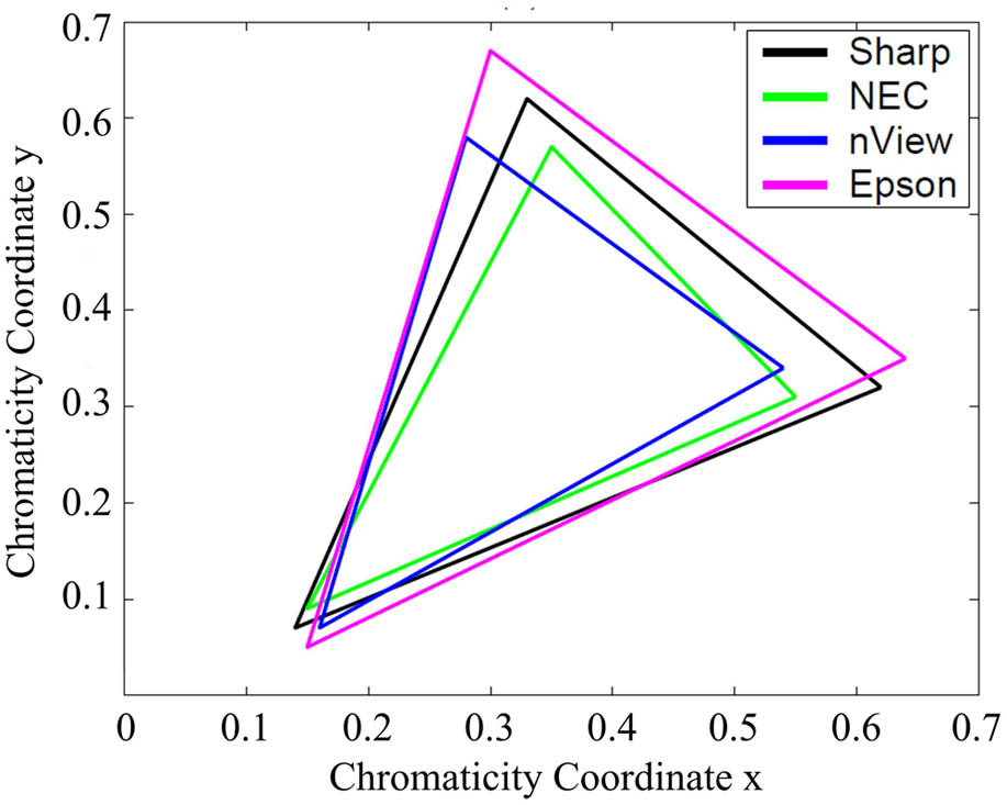
The entire range of chrominance that can be reproduced by a display is represented as the color gamut of the display. Figure 1 illustrates the color gamut of four projectors of different brands, in which each projector contains colors that cannot be produced by the other projectors[8]. When given identical input, the colors generated by a certain projector will be different from those generated by the others. The differences in the output cause visible variations across the projected image. Measures need to be taken to make sure that the projectors produce the same color when given identical input.
There are two conventional ways to match different color gamuts; these are gamut cutting and gamut compressing[9]. Gamut cutting uses colors on its borders to represent those colors that are outside of it; the colors inside the gamut will not be changed. Gamut compressing maps all the colors according to the properties of the original and target gamuts. In this Letter, a color-matching algorithm that maps all the gamuts of the projectors in the system to a common color gamut is proposed to ensure identical color reproduction across the system.
Let the color formed by a single channel input be ; hence, . Let be the desired color. A per-channel scale factor of () can be found for each projector, such that:
Based on the above discussion, gamut matching can be accomplished in three steps: Select a common color gamut for the system. Three vertices (inside all the color gamuts and represented as , , and ) are picked to determine this gamut. The colors within this gamut will then be represented through the chromaticity coordinates of the three vertices, which are regarded as the tristimulus values of this new, “common color space.” Figure 2 shows an example of a common gamut selection. Given the chromaticity coordinates of a newly picked tristimulus value, for example: for , three scaling factors will be calculated using Eq. (3). These scaling factors can be easily transformed into the RGB color space, and are represented as . To calculate the scaling factors, is first set to 1. Solving the other two linear equations will yield and . If this leads to a value of that is not between 0 and 1, then the process will be repeated with either or .Choose a white point for the common color gamut. Calculate three scaling factors for each channel using Eq. (3).When the target color is determined, the corresponding input for each projector can be calculated through the following equation: where represents the target color that the system needs to generate and matrix represents the map of the path from the target color to the input of the th projector.
Figure 2.Selecting common color gamut. (a) Gamuts of two projectors. (b) Selected common gamut.
After gamut matching, the chrominance of the system will be consistent through the whole composite image, while the luminance remains fluctuant. In the second stage, a constraint-smoothing optimization will be introduced to calculate the luminance attenuation for each projector pixel so that the luminance will transit smoothly through the overlapping region.
When dealing with the systems that contain irregularly shaped overlapping regions, traditional smoothing methods such as linear attenuation or gamma attenuation become impractical, since it is hard to find the direction of attenuation. In order to compensate for the shortcomings of the conventional solutions, a light transport matrix-based optimization is adopted to calculate the luminance attenuation for each projector pixel.
The light transport between projectors with a resolution and a camera with a resolution is modeled by a matrix[14], which can be mathematically expressed as Here, the column vector is the projected image (with the dimension of ), (with the dimension of ) represents the image captured by the camera, and matrix (with the dimension of ) is the transport matrix that describes how light from each pixel of arrives at each pixel of , taking into account all global illumination. Figure 3 shows the makeup of the light transport matrix.
When dealing with a single projector, a unique pseudo-inverse value of can be easily computed by bounding the intensity value of each pixel between [0,1]. The intensity is then multiplied by the maximum pixel value. For the multi-projector case, the problem must be carefully constrained so as to obtain an optimal solution[15]. Figure 4 shows a simple example with several possible compensation solutions when using multiple projectors. It can be seen from Fig. 4 that the inversion of must take into account the illumination capabilities of the projectors so the optimization will not yield intensities that cannot be projected [see Fig. 4(c)]. In addition, smoothness constraints are necessary to avoid unnecessary undulations[16] [see Fig. 4(d)].
Figure 4.Multi-projector constrained optimization. (a) Target Luminance. (b) Two Projectors 1. (c) Two Projectors 2. (d) Two Projectors 3.
To ensure the image quality, the best combination of the projector inputs should be found to minimize the difference between the achieved appearance and the target high-resolution appearance. Minimizing yields a high-resolution appearance that is closest to the target image. In order to find the best solution for this optimization, two constraints must be satisfied: The input values must be clipped to [0,1]. This clipping assures the best possible solutions that avoid underflowing and overflowing intensities.Smoothing constraints should be introduced to assure that the neighboring pixels from any one projector have smoothly changing compensation values. The weights of the smooth constraints should be inversely proportional to the difference of the intensities in the target image, so the constraints can be written as The weight is defined as where is the ratio of the target image intensity to the observed intensity of the projector pixel. Aliaga et al. used this optimization to calculate the scaled compensating image for a textured-surface projection system[15]. Their method will be adopted to find the smooth luminance attenuation for each pixel here.
In this Letter, the elements of will be set to 1, according to the geometrical map. will be replaced by the target image, and is the unknown that is going to be solved for. Solving the optimization will result in a per-pixel scaling factor .
Let be the image generated in the projector coordinate system after applying the geometric map and gamut matching. To achieve the color correction, must be multiplied in pixel-wise values with the attenuation map to generate an appropriately scaled , such that
Since the projectors are not linear devices, the final step of correction is to apply the inverse of the input transfer function[6].
Two Sanyo XU1060C projectors and a car model made of plaster as shown in Fig. 5(a) are used for the projection experiment. In order to compensate for the color variation of the irregularly shaped overlapping region across adjacent projectors caused by the non-planar surface of the car model, geometric and chrominance matching along with the luminance attenuation map are first calculated in an offline step. The calculation takes about 10 min. Then, the calibration parameters are stored in the graphics rendering lines. An online image correction is achieved in real time using a graphics processing unit through XNA (a graphics rendering engine announced by Microsoft). Figure 5 shows the result of the correction. Figure 6 shows the comparison of the projections before and after gamut matching. It can be seen from Fig. 6 that the color variations will be eliminated after gamut matching. Figure 7 shows two frames of a video rendered onto the car model in the rate of 30 FPS.
Figure 5.Results of correction. (a) Setup of the system. (b) Before correction. (c) After geometric calibration. (d) After color correction.
Figure 6.Results of gamut matching. (a) Before gamut matching (red). (b) After gamut matching (red). (c) Before gamut matching (green). (d) After gamut matching (green).
The coefficients of variation (CVs) in Tables 1 and 2 and in Fig. 8 are calculated with relative luminance[17] (the luminance values are set to 0 when the output value of the camera with a certain exposure is 128), which has the unit of with a scaling factor. Table 1 shows the comparison between luminance consistencies. In Ref. [18], the surface normal-based method is adopted to calculate the attenuation map for the pixels, and it performs well when the surface is spherical or cylindrical. However, when it comes to the car model, the margin areas of the overlapping region show a certain discontinuity, which varies with the accuracy of the geometric map, whereas the proposed method performs better at both the marginal and central areas of the overlap due to the rigid smoothness constraint. Table 2 shows the comparison between color consistenies. Sajadi[13] manages to achieve color smoothness through gamut morphing, which enlarges the luminance range of the system while ensuring smooth color transit. However, if the overlapping region is not wide enough, the variations in color will not be fully removed. Our proposed method adopts strict color matching, which makes the correction scheme independent of the shape of the overlapping region. Figure 8 shows the color consistency before and after the correction. It can be seen from Fig. 8 that the deviation of the color after correction is relatively small, which ensures that viewers will not perceive any color variation in the system. The variation becomes larger as the input gets lower; this is because there is a light leak even when the input from the projector is zero. As the input gets larger, the impact of the light leak decreases.
CV
Region
Our Method
Peter 2011[18]
Margin
1.93%
4.35%
Center
1.76%
1.88%
Table 1. CV of the Luminance at the Marginal and Central Areas of the Overlapping Region
In conclusion, the algorithm proposed can eliminate color variation in systems that contain an irregularly overlapping region. Common color gamut-based chrominance correction ensures that different projectors produce same color when given a certain input so as to eliminate the chrominance differences. Constrained optimization generates a smooth attenuation weight for each projector pixel, and ensures that the luminance transits smoothly through the overlapping region. The experimental results show that the proposed algorithm performs better than the existing methods that deal with color variation in an irregularly shaped overlapping region.
Due to the massive size of the light transform matrix, the optimization takes more time than expected. Future research should focus on dealing with this problem.
Feng Chen, Yue Liu, Tao Yang. Color correction for tiled projection with irregularly shaped, overlapping region[J]. Chinese Optics Letters, 2015, 13(9): 093301