
Jitendra Narayan Dash, Xin Cheng, Dinusha Serandi Gunawardena, Hwa-Yaw Tam, "Rectangular single-mode polymer optical fiber for femtosecond laser inscription of FBGs," Photonics Res. 9, 1931 (2021)
- Photonics Research
- Vol. 9, Issue 10, 1931 (2021)
Abstract
1. INTRODUCTION
Femtosecond (fs) lasers offer an exciting new technology that permits the fabrication of various kinds of novel optical devices in optical fibers, including gratings, optical waveguides, miniature sensors, and interferometers [1–3]. The attraction of the fs laser based grating is driven by its unique advantages such as grating inscription without a phase mask and ability to inscribe gratings in any type of optical fiber including non-photosensitive fibers and different patterns of grating pitch [4]. In addition, the short duration of the pulses enables one to precisely control the spatial dimension of the refractive index (RI) modulation region in optical fiber [5]. Owing to the above advantages, fs laser based gratings have been inscribed in a wide variety of silica based fibers for various sensing applications [6–8]. Although, a silica based fiber Bragg grating (FBG) can be used to measure various physical parameters, its high Young’s modulus (
Recently, fs lasers have been utilized in the fabrication of FBGs in PMMA and CYTOP multi-mode fibers [9,19,31,35–37]. Point-by-point (PbP) and line-by-line (LBL) inscription techniques demonstrated in these studies eliminate the need for phase masks. It is to be noted that the phase mask technique is useful for repeatable inscription of FBGs at specific wavelengths, while the PbP technique permits tailoring of the Bragg wavelength for FBG inscription at different orders or different wavelengths depending on the requirement of the sensing application. However, the focused fs laser beam experiences distortion effects when passing through a circular fiber that acts as a cylindrical lens. The lensing effect causes the laser beam to be more elongated as it moves towards the fiber core, which reduces laser intensity. The distortion also makes visualization of the fiber rather difficult. The lensing distortions can be diminished by immersing the optical fiber in index-matching (IM) oil and sandwiching it between two thin glass slides. Alternatively, a section of fiber can be polished down to a
In this paper, we propose a novel rectangular POF to diminish the lensing distortion, thereby avoiding the use of IM oil during FBG inscription using the fs laser. The main challenge is designing and fabricating a rectangular fiber with flat surfaces since a small variation in the writing plane (
Sign up for Photonics Research TOC. Get the latest issue of Photonics Research delivered right to you!Sign up now
2. RECTANGULAR OPTICAL FIBER FABRICATION AND FLATNESS CHARACTERIZATION
A. Fabrication of ZEONEX Rectangular Optical Fiber
The rectangular optical fiber preform was fabricated using the pull through method [10]. The core and cladding of the fiber were made of different grades of ZEONEX, namely, ZEONEX E48R and ZEONEX 480R, respectively [10,11,31]. The RI of E48R is 1.531 (at
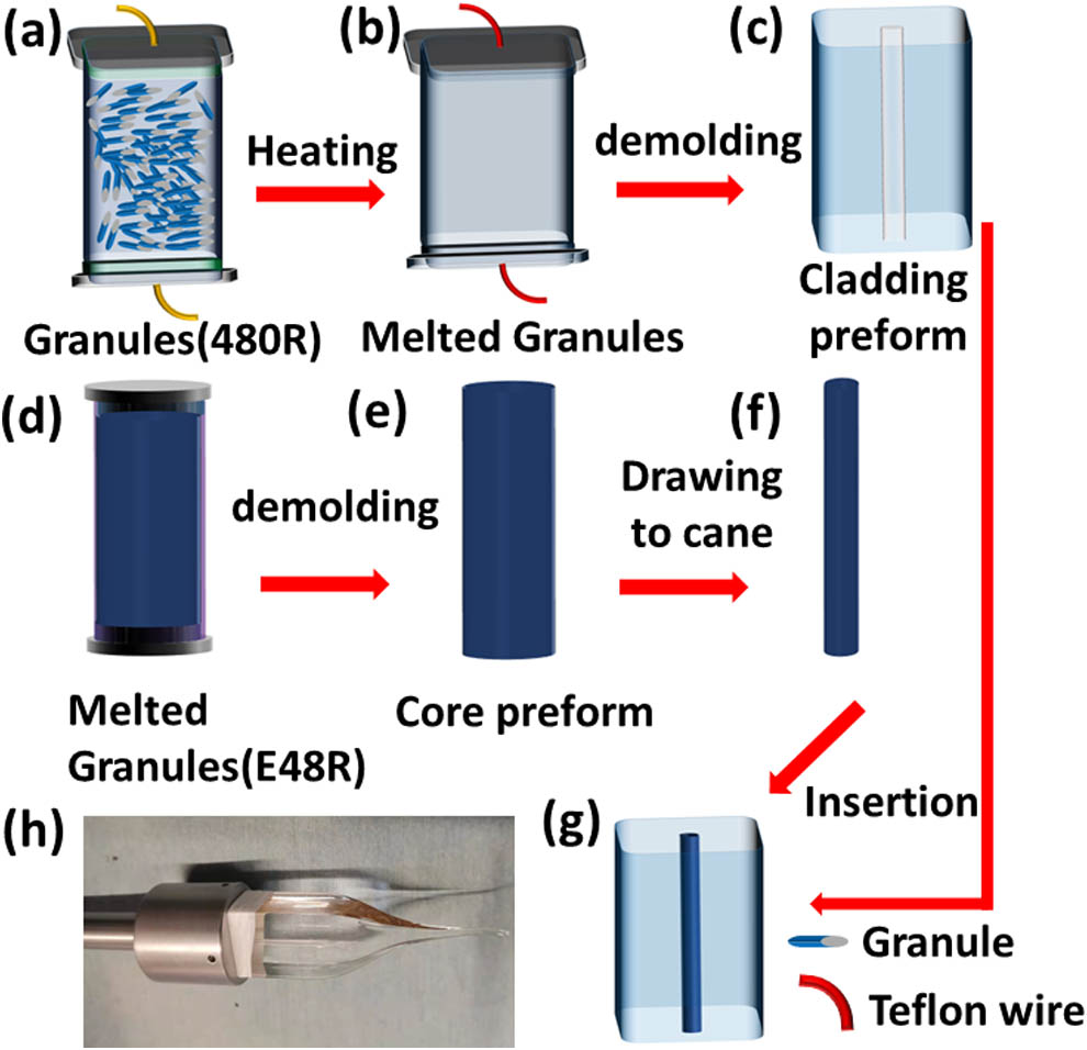
Figure 1.(a)–(g) Fabrication procedure of ZEONEX based rectangular polymer optical fiber preform and (h) image of the rectangular preform after a segment of it was drawn into rectangular optical fiber.
![]()
Figure 2.(a) Cross section of the ZEONEX rectangular optical fiber with light guidance through the core and (b) simulated profile of the core mode.
B. Surface Flatness Characterization
The surface of the rectangular optical fiber through which the fs laser beam is focused onto the core must be extremely flat to avoid any distortion of the laser beam. This is because a small change in the flatness of the writing plane (x–z plane as shown in Fig. 3) during FBG fabrication may affect the FBG spectrum. A second harmonic beam from the fs laser (Spectra-Physics Spirit One) at an emission wavelength of 520 nm with a repetition rate of 100 Hz and a pulse duration of 250 fs was used in the FBG fabrication process. A
![]()
Figure 3.3D surface profile measurement result of the ZEONEX rectangular optical fiber.
A laser scanning confocal microscope capable of measuring surface roughness with nanometer resolution (Keyence’s VK-X200) was used to conduct an area scan of the fiber surface. The surface of the rectangular optical fiber was sputter coated with a 25-nm layer of gold to increase the contrast of the measurement. Figure 3 shows the 3D measurement results of the fiber surface covering
3. RESULTS AND DISCUSSION
A. FBG Inscription Process and Focusing of Laser Beam onto Circular and Rectangular Fibers
The laser beam passed through a half-wave plate followed by a Glan laser polarizer, collimator, and quarter-wave plate and then was reflected from a dichroic mirror before being focused onto the fiber. The reflected beam was then focused onto the fiber by a
Prior to FBG inscription, investigations were carried out to ensure optimal focusing of the laser beam onto circular and rectangular optical fibers. In addition, the effect of incorporating IM oil was explored as well. When the laser beam is focused onto the circular fiber in the absence of IM oil, a focal mismatch occurs (astigmatism) between the axial (parallel to the fiber axis) [see Fig. 4(a)] and radial (perpendicular to the fiber axis) [see Fig. 4(b)] parts of the laser beam. In other words, when the radial beam is focused onto the core, the axial beam is focused outside the core. Due to the cylindrical geometry of the fiber, optical confinement of light at the radially focused region is higher compared to that of the axial beam resulting in a higher laser induced RI modification in the former. When both these effects are taken into consideration simultaneously, the region of inscription in the fiber core will be axially elongated as shown in Fig. 4(a). The microscope image of the elongated laser beam induced inscription region is shown in Fig. 4(c). However, in the presence of IM oil, the error introduced by curvature is eliminated and both parts of the beam, axial and radial, are focused onto a single point. The corresponding microscope image is shown in Fig. 4(d). On the contrary, there is no focal mismatch between the axial and radial parts of the laser beam due to the flat surface of the rectangular fiber as shown in Figs. 5(a) and 5(b), respectively. Therefore, this leads to the formation of a point focal region as shown in Fig. 5(a). It should be noted that there is a possibility of an intensity reduction of the laser beam due to the surface roughness at the core–cladding interface. To further evaluate the degree of focus of the laser beam on the rectangular fiber, FBGs were inscribed in this fiber in the absence and presence of IM oil as shown in Figs. 6(a) and 6(b), respectively. The lower contrast and slight deviation from a point shape in Fig. 6(a) may be attributed to the negligible nonuniformity of the flat surface of the rectangular fiber. The spectra corresponding to the FBG inscribed in a circular fiber with oil and in a rectangular fiber without and with oil are shown in Figs. 6(c)–6(e). Figure 6(f) illustrates the cross section of a segment of the grating shown in Fig. 6(a). It can be clearly seen that the damage region extends from the fiber core to a part of the cladding, and the irradiated region has a rectangular shape of which the length and width were found to be 9.66 μm and 1.44 μm, respectively. This type of elongated spot arises due to the Gaussian nature of the focused beam as shown in Fig. 6(g).
![]()
Figure 4.Schematic illustrations of (a) axial (side view) and (b) radial (cross sectional view) aspects of the focused laser beam onto a circular fiber without IM oil. The red region in (a) indicates the elongated focal region. Microscope images of fs laser inscribed regions in circular fiber in (c) the absence and (d) presence of IM oil.
![]()
Figure 5.Schematic illustrations of (a) axial (side view) and (b) radial (cross sectional view) parts of focused laser beam onto the rectangular fiber without IM oil.
![]()
Figure 6.Microscope images of FBGs inscribed in ZEONEX rectangular fiber (a) without and (b) with IM oil. Reflection spectra of the inscribed FBGs (c) with IM oil in circular fiber, (d) without and (e) with IM oil in rectangular fiber. (f) Cross sectional view of the grating in (a), where the red dashed circle refers to the core and the black line refers to the laser irradiated region. (g) Schematic illustration of the focused laser beam in Gaussian form, and the red arrow shows the beam direction.
B. Characterization of FBGs
Initially, the FBG was inscribed in a ZEONEX based rectangular fiber with the aid of a 248-nm excimer laser (Bragg Star) and a phase mask (Ibsen, 1027.6 nm). A 2-mm-long grating was inscribed in these fibers with two pulses, each having a pulse energy of 65 mJ and pulse duration of 25 ns. A broadband supercontinuum light source (YSL Photonics) was used to couple light to the FBGs inscribed in the rectangular fibers, and the corresponding reflection spectra are shown in Fig. 7. It is apparent from the figure that the reflection spectrum of the FBG has only a single peak at 1555.9 nm (effective index
![]()
Figure 7.Reflection spectrum of the FBG inscribed in ZEONEX rectangular fiber using 248-nm UV laser and phase mask technique.
![]()
Figure 8.Reflection spectrum of the FBG inscribed in ZEONEX rectangular fiber using fs laser exhibiting peaks at 866.8, 1013, and 1511.3 nm.
Afterwards, the strain and temperature responses of the FBGs inscribed using the aforementioned procedure were investigated. A segment of the ZEONEX rectangular fiber inscribed with an FBG was butt coupled to a silica fiber. The two ends of the FBG in the rectangular fiber were fixed onto two translational stages (MAX350/M, Thorlabs) as shown in Fig. 9. The distance between the glue point and the FBG was fixed at 1 cm. One of the stages was kept stationary while the other (1-μm resolution) was moved away from the FBG for application of strain. Light from a broadband supercontinuum source (YSL Photonics) was coupled to the FBG using an optical coupler, and the reflected light was analyzed using an optical spectrum analyzer (OSA, AQ6370D, Yokogawa, resolution = 0.02 nm). The peaks corresponding to 866.8 and 1511.3 nm can be simultaneously monitored using an OSA, although different interrogators can be used for each wavelength depending on the application. The strain introduced to the fiber was increased from 0% to 1% and then decreased from 1% to 0%, and this process was repeated for three cycles. The spectral response of the FBG peak (1511.3 nm) to the applied strain is shown in Fig. 10(a), and the shift in the FBG peak wavelength for three cycles is shown in Fig. 10(b). The average strain sensitivity after three cycles of measurement was found to be
![]()
Figure 9.Experimental setup for strain measurement. Inset shows the FBG under investigation and the glued localities of the fiber. ZRF, ZEONEX based rectangular fiber; BBS, broadband source.
![]()
Figure 10.(a) Spectral shift of the FBG peak (1511.3 nm) with applied strain. (b) Wavelength shift of the FBG peak with increasing and decreasing strain for three cycles of measurement with 1% change in strain for each cycle.
Following the same procedure, the spectral response of the FBG peak corresponding to 866.8 nm is plotted in Fig. 11(a), and the shift in FBG peak wavelength for three cycles of measurement is shown in Fig. 11(b). The average strain sensitivity in this scenario was found to be
![]()
Figure 11.(a) Spectral shift of the FBG peak (866.8 nm) with applied strain. (b) Wavelength shift of the FBG peak with increasing and decreasing strain for three cycles of measurement with 1% change in strain for each cycle.
| Temperature Sensitivity | ||
|---|---|---|
| TOPAS [ | –78 pm/°C | |
| CYTOP [ | 11.2 pm/°C | |
| PMMA [ | –54.50 pm/°C | |
| PC [ | –29.99 pm/°C | |
| ZEONEX [ | –9.78 pm/°C | |
| ZEONEX [ | –24.7 pm/°C | |
| ZEONEX mPOF [ | –24.01 pm/°C | |
| This work (ZEONEX) | –10 pm/°C | |
| –15 pm/°C |
Table 1. Comparison of Strain and Temperature Responses of POFBGs
The temperature responses of the FBG peaks corresponding to 866.8 and 1511.3 nm were analyzed by placing the sensor inside a tube furnace. The temperature was increased from 20°C to 60°C in intervals of 10°C. The linear temperature responses of the FBG are shown in Figs. 12(a) and 12(b). The temperature sensitivity of the peak corresponding to 866.8 nm was found to be 10 pm/°C, while that corresponding to 1511.3 nm peak was found to be 15 pm/°C. Table 1 shows the temperature response of the proposed probe along with other previously reported results.
![]()
Figure 12.Wavelength shift of the FBG corresponding to peaks at (a) 1511.3 nm and (b) 866.8 nm with increasing temperature.
4. CONCLUSION
We have demonstrated fs laser inscribed FBGs in a novel rectangular shaped single-mode POF in which the core and cladding were composed of different grades of ZEONEX that ensured the fiber to be dopant free. The rectangular fiber with a good surface profile was drawn using the in-house fiber drawing facility. In contrast to their circular counterparts, the flat surface and the geometry of the rectangular fiber aid in the inscription of FBGs using the PbP technique without the requirement for IM oil, thereby significantly reducing the FBG inscription time, which greatly benefits mass production of FBGs. Fabrication of a single FBG led to the excitation of three different FBG peaks corresponding to different orders over the wavelength range from 800 to 1600 nm, out of which one was at 866.8 nm, where the transmission loss for ZEONEX is less, and the other was at 1511.4 nm. This process avoids the necessity for inscription of two individual gratings for different wavelengths, thereby once again contributing to a reduced FBG inscription time. The strain and temperature responses of the grating were also analyzed, and the sensitivities were found to be
References
[1] G. D. Marshall, R. J. Williams, N. Jovanovic, M. J. Steel, M. J. Withford. Point-by-point written fiber-Bragg gratings and their application in complex grating designs. Opt. Express, 18, 19844-19859(2010).
[2] Y. Zhang, C. Liao, C. Lin, Y. Shao, Y. Wang, Y. Wang. Surface plasmon resonance refractive index sensor based on fiber-interface waveguide inscribed by femtosecond laser. Opt. Lett., 44, 2434-2437(2019).
[3] Q. Wang, H. Zhang, D. N. Wang. Cascaded multiple Fabry–Perot interferometers fabricated in no-core fiber with a waveguide for high-temperature sensing. Opt. Lett., 44, 5145-5148(2019).
[4] T. Geernaert, K. Kalli, C. Koutsides, M. Komodromos, T. Nasilowski, W. Urbanczyk, J. Wojcik, F. Berghmans, H. Thienpont. Point-by-point fiber Bragg grating inscription in free-standing step-index and photonic crystal fibers using near-IR femtosecond laser. Opt. Lett., 35, 1647-1649(2010).
[5] B. N. Chichkov, C. Momma, S. Nolte, F. von Alvensleben, A. Tünnermann. Femtosecond, picosecond and nanosecond laser ablation of solids. Appl. Phys. A, 63, 109-115(1996).
[6] X. Fang, C. R. Liao, D. N. Wang. Femtosecond laser fabricated fiber Bragg grating in microfiber for refractive index sensing. Opt. Lett., 35, 1007-1009(2010).
[7] W. Cui, J. Si, T. Chen, X. Hou. Compact bending sensor based on a fiber Bragg grating in an abrupt biconical taper. Opt. Express, 23, 11031-11036(2015).
[8] Z. Chen, L. Yuan, G. Hefferman, T. Wei. Terahertz fiber Bragg grating for distributed sensing. IEEE Photon. Technol. Lett., 27, 1084-1087(2015).
[9] X. Hu, D. Kinet, K. Chah, C.-F. J. Pun, H.-Y. Tam, C. Caucheteur. Bragg grating inscription in PMMA optical fibers using 400-nm femtosecond pulses. Opt. Lett., 42, 2794-2797(2017).
[10] X. Cheng, D. S. Gunawardena, C.-F. J. Pun, J. Bonefacino, H.-Y. Tam. Single nanosecond-pulse production of polymeric fiber Bragg gratings for biomedical applications. Opt. Express, 28, 33573-33583(2020).
[11] G. Woyessa, H. K. Rasmussen, O. Bang. Zeonex—a route towards low loss humidity insensitive single-mode step-index polymer optical fibre. Opt. Fiber Technol., 57, 102231(2020).
[12] R. Ishikawa, H. Lee, A. Lacraz, A. Theodosiou, K. Kalli, Y. Mizuno, K. Nakamura. Pressure dependence of fiber Bragg grating inscribed in perfluorinated polymer fiber. IEEE Photon. Technol. Lett., 29, 2167-2170(2017).
[13] Y. Luo, Q. Zhang, H. Liu, G.-D. Peng. Gratings fabrication in benzildimethylketal doped photosensitive polymer optical fibers using 355 nm nanosecond pulsed laser. Opt. Lett., 35, 751-753(2010).
[14] J. Bonefacino, H.-Y. Tam, T. S. Glen, X. Cheng, C.-F. J. Pun, J. Wang, P.-H. Lee, M.-L. V. Tse, S. T. Boles. Ultra-fast polymer optical fibre Bragg grating inscription for medical devices. Light Sci. Appl., 7, 17161(2018).
[15] W. Yuan, L. Khan, D. J. Webb, K. Kalli, H. K. Rasmussen, A. Stefani, O. Bang. Humidity insensitive TOPAS polymer fiber Bragg grating sensor. Opt. Express, 19, 19731-19739(2011).
[16] R. Min, B. Ortega, A. Leal-Junior, C. Marques. Fabrication and characterization of Bragg grating in CYTOP POF at 600-nm wavelength. IEEE Sens. Lett., 2, 5000804(2018).
[17] I.-L. Bundalo, K. Nielsen, G. Woyessa, O. Bang. Long-term strain response of polymer optical fiber FBG sensors. Opt. Lett., 7, 967-976(2017).
[18] A. Stefani, S. Andresen, W. Yuan, O. Bang. Dynamic characterization of polymer optical fibers. IEEE Sens. J., 12, 3047-3053(2012).
[19] A. Lacraz, A. Theodosiou, K. Kalli. Femtosecond laser inscribed Bragg grating arrays in long lengths of polymer optical fibres; a route to practical sensing with POF. Electron. Lett., 52, 1626-1627(2016).
[20] A. Leal-Junior, A. Frizera, M. J. Pontes, A. Fasano, G. Woyessa, O. Bang, C. A. F. Marques. Dynamic mechanical characterization with respect to temperature, humidity, frequency and strain in mPOFs made of different materials. Opt. Mater. Express, 8, 804-815(2018).
[21] J. N. Dash, X. Cheng, H. Y. Tam. Low gas pressure sensor based on polymer optical fiber grating. Opt. Lett., 46, 933-936(2021).
[22] D. Sáez-Rodríguez, K. Nielsen, H. K. Rasmussen, O. Bang, D. J. Webb. Highly photosensitive polymethyl methacrylate microstructured polymer optical fiber with doped core. Opt. Lett., 38, 3769-3772(2013).
[23] X. Hu, G. Woyessa, D. Kinet, J. Janting, K. Nielsen, O. Bang, C. Caucheteur. BDK-doped core microstructured PMMA optical fiber for effective Bragg grating photo-inscription. Opt. Lett., 42, 2209-2212(2017).
[24] L. Pereira, R. Min, X. Hu, C. Caucheteur, O. Bang, B. Ortega, C. Marques, P. Antunes, J. L. Pinto. Polymer optical fiber Bragg grating inscription with a single Nd:YAG laser pulse. Opt. Express, 26, 18096-18104(2018).
[25] A. Fasano, G. Woyessa, P. Stajanca, C. Markos, A. Stefani, K. Nielsen, H. K. Rasmussen, K. Krebber, O. Bang. Fabrication and characterization of polycarbonate microstructured polymer optical fibers for high-temperature-resistant fiber Bragg grating strain sensors. Opt. Mater. Express, 6, 649-659(2016).
[26] G. Woyessa, A. Fasano, C. Markos, H. K. Rasmussen, O. Bang. Low loss polycarbonate polymer optical fiber for high temperature FBG humidity sensing. IEEE Photon. Technol. Lett., 29, 575-578(2017).
[27] G. Emiliyanov, J. B. Jensen, P. E. Hoiby, L. H. Pedersen, E. M. Kjaer, L. Lindvold, O. Bang. Localized biosensing with TOPAS microstructured polymer optical fiber. Opt. Lett., 32, 460-462(2007).
[28] G. Emiliyanov, P. E. Høiby, L. H. Pedersen, O. Bang. Selective serial multi-antibody biosensing with TOPAS microstructured polymer optical fibers. Sensors, 13, 3242-3251(2013).
[29] G. Woyessa, A. Fasano, C. Markos, A. Stefani, H. K. Rasmussen, O. Bang. ZEONEX microstructured polymer optical fiber: fabrication friendly fibers for high temperature and humidity insensitive Bragg grating sensing. Opt. Mater. Express, 7, 286-295(2017).
[30] G. Woyessa, J. K. M. Pedersen, A. Fasano, K. Nielsen, C. Markos, H. K. Rasmussen, O. Bang. ZEONEX-PMMA microstructured polymer optical FBGs for simultaneous humidity and temperature sensing. Opt. Lett., 42, 1161-1164(2017).
[31] P. Akrami, A. I. Adamu, G. Woyessa, H. K. Rasmussen, O. Bang, C. Markos. All-polymer multimaterial optical fiber fabrication for high temperature applications. Opt. Mater. Express, 11, 345-354(2021).
[32] A. Lacraz, M. Polis, A. Theodosiou, C. Koutsides, K. Kalli. Femtosecond laser inscribed Bragg gratings in low loss CYTOP polymer optical fiber. IEEE Photon. Technol. Lett., 27, 693-696(2015).
[33] G. Zhou, C. J. Pun, H. Tam, S. Member, A. C. L. Wong, C. Lu, P. K. A. Wai. Single-mode perfluorinated polymer optical fibers applications. IEEE Photon. Technol. Lett., 22, 106-108(2010).
[34] G. Woyessa, A. Fasano, A. Stefani, C. Markos, K. Nielsen, H. K. Rasmussen, O. Bang. Single mode step-index polymer optical fiber for humidity insensitive high temperature fiber Bragg grating sensors. Opt. Express, 24, 1253-1260(2016).
[35] A. Leal-Junior, A. Theodosiou, A. Frizera-Neto, M. J. Pontes, E. Shafir, O. Palchik, N. Tal, S. Zilberman, G. Berkovic, P. Antunes, P. André, K. Kalli, C. Marques. Characterization of a new polymer optical fiber with enhanced sensing capabilities using a Bragg grating. Opt. Lett., 43, 4799-4802(2018).
[36] A. Theodosiou, A. Lacraz, A. Stassis, C. Koutsides, M. Komodromos, K. Kalli. Plane-by-plane femtosecond laser inscription method for single-peak Bragg gratings in multimode CYTOP polymer optical fiber. J. Lightwave Technol., 35, 5404-5410(2017).
[37] A. G. Leal, A. Frizera, A. Theodosiou, C. Díaz, M. Jimenez, R. Min, M. J. Pontes, K. Kalli, C. Marques. Plane-by-plane written, low-loss polymer optical fiber Bragg grating arrays for multiparameter sensing in a smart walker. IEEE Sens. J., 19, 9221-9228(2019).
[38] J. Zhou, Z. Zhou, D. Zhang. Study on strain transfer characteristics of fiber Bragg grating sensors. J. Intell. Mater. Syst. Struct., 21, 1117-1122(2010).
[39] H. P. Wang, P. Xiang, X. Li. Theoretical analysis on strain transfer error of FBG sensors attached on steel structures subjected to fatigue load. Strain, 52, 522-530(2016).
[40] C. D. Hussey, F. Martinez. Approximate analytical forms for the propagation characteristics of single-mode optical fibres. Electron. Lett., 21, 1103-1104(1985).


Set citation alerts for the article
Please enter your email address

© Copyright 2018-2021 | Chinese Laser Press. All Rights Reserved 沪ICP备15018463号-20