• Photonics Research
  • Vol. 6, Issue 9, 847 (2018)
Xianyou Wang1、†, Yuquan Zhang1、†, Yanmeng Dai1, Changjun Min1、2、*, and Xiaocong Yuan1、3、*
Author Affiliations
  • 1Nanophotonics Research Center, Shenzhen Key Laboratory of Micro-Scale Optical Information Technology, Shenzhen University, Shenzhen 518060, China
  • 2e-mail: cjmin@szu.edu.cn
  • 3e-mail: xcyuan@szu.edu.cn
  • show less
    DOI: 10.1364/PRJ.6.000847 Cite this Article Set citation alerts
    Xianyou Wang, Yuquan Zhang, Yanmeng Dai, Changjun Min, Xiaocong Yuan. Enhancing plasmonic trapping with a perfect radially polarized beam[J]. Photonics Research, 2018, 6(9): 847 Copy Citation Text show less
    Dynamic plasmonic tweezer system construction and two types of excitation optical beam generation. (a) Technical schematic of the generating RPB and PRPB for the optical tweezer system. The RPB generated by vortex retarder (VR) is also the PRPB generated by changing telescope system (L3, L4) with two axicons (A1, A2). (b) Technical schematic of the SPP excitation process for a focusing RPB. The black arrows indicate the radial polarization directions. (c) The profile of the reflected light obtained at the back focal plane for RPB. (e) The profile of the reflected light obtained at the back focal plane for PRPB.
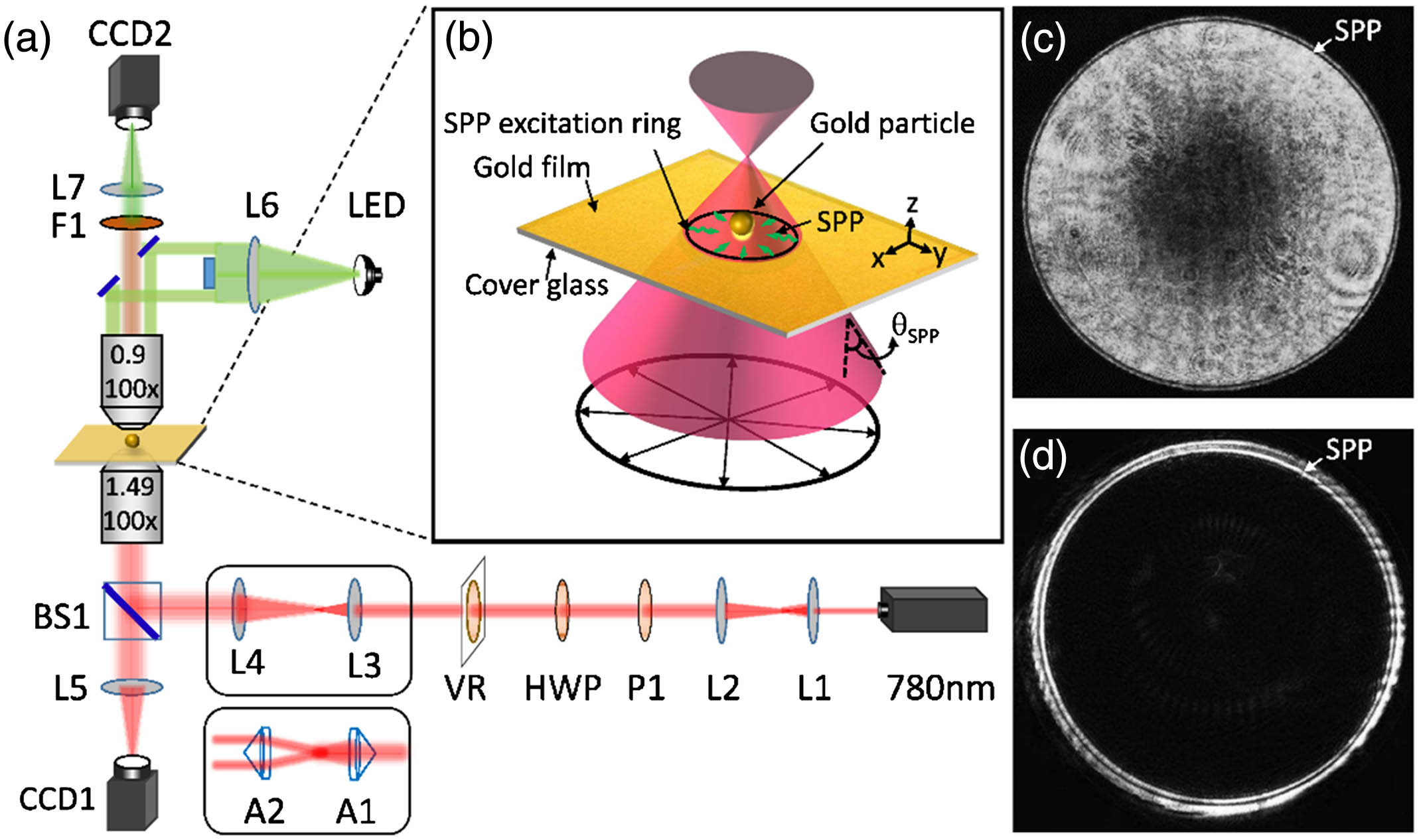
    Fig. 1. Dynamic plasmonic tweezer system construction and two types of excitation optical beam generation. (a) Technical schematic of the generating RPB and PRPB for the optical tweezer system. The RPB generated by vortex retarder (VR) is also the PRPB generated by changing telescope system (L3, L4) with two axicons (A1, A2). (b) Technical schematic of the SPP excitation process for a focusing RPB. The black arrows indicate the radial polarization directions. (c) The profile of the reflected light obtained at the back focal plane for RPB. (e) The profile of the reflected light obtained at the back focal plane for PRPB.
    Calculated electric field intensities at the gold–water interface for focused RPB and PRPB. (a), (b), (c) Cross-section distribution and focused state for RPB, PRPB and RPB with no SPP excitation mode. (d), (g) Electric field intensities at the gold–water interface (horizontal x-y plane) and in the x-z plane for RPB. (e), (h) Electric field intensities at the gold–water interface (x-y plane) and in the x-z plane for the PRPB. (f), (i) Electric field intensities at the gold–water interface (x-y plane) and in the x-z plane for the RPB with no SPP excitation mode. The white lines in the bottom of (g), (h), and (i) indicate the gold–water interface.
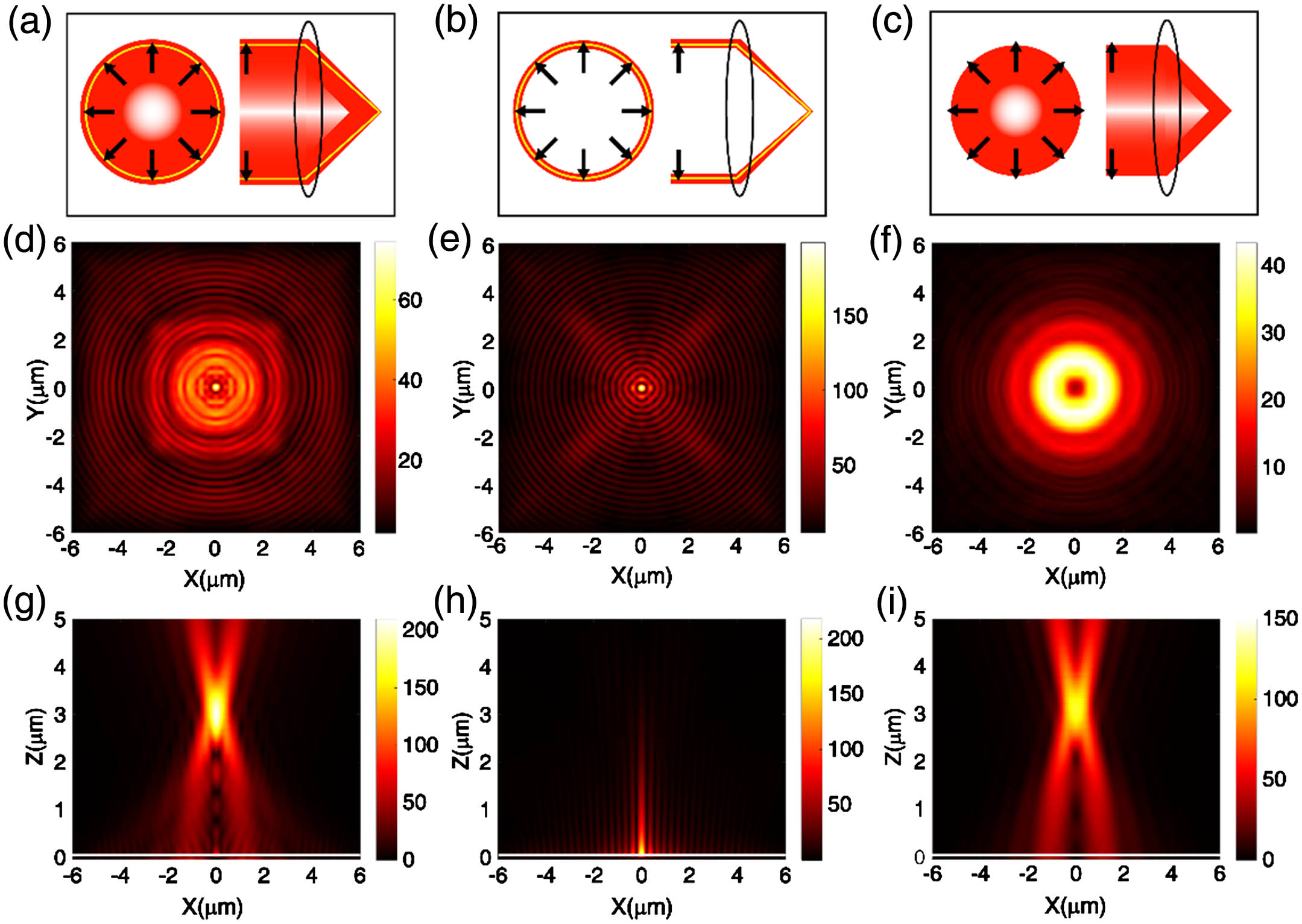
    Fig. 2. Calculated electric field intensities at the gold–water interface for focused RPB and PRPB. (a), (b), (c) Cross-section distribution and focused state for RPB, PRPB and RPB with no SPP excitation mode. (d), (g) Electric field intensities at the gold–water interface (horizontal x-y plane) and in the x-z plane for RPB. (e), (h) Electric field intensities at the gold–water interface (x-y plane) and in the x-z plane for the PRPB. (f), (i) Electric field intensities at the gold–water interface (x-y plane) and in the x-z plane for the RPB with no SPP excitation mode. The white lines in the bottom of (g), (h), and (i) indicate the gold–water interface.
    Calculated force distributions at the gold–water interface for the focused RPB and PRPB. (a) Distributing curve of force for gold particles in the radial direction with the RPB and PRPB. (b) Distributing curve of force for gold particles in axial direction with the RPB and PRPB.
    Fig. 3. Calculated force distributions at the gold–water interface for the focused RPB and PRPB. (a) Distributing curve of force for gold particles in the radial direction with the RPB and PRPB. (b) Distributing curve of force for gold particles in axial direction with the RPB and PRPB.
    Position tracking and power spectra analysis of the trapped gold particles with a diameter of 1±0.5 μm for (a)–(c) RPB and (d)–(f) PRPB. The laser powers at the BFP are about 13.9 mW and 12.4 mW for the RPB and PRPB, respectively. (a) Scattering distribution of the position for the gold particle in RPB. (b) Displacement of the particle versus time for RPB. (c) The power spectra of the particle for RPB fitting with a Lorentzian curve. (d) Scattering distribution of the position for the gold particle in PRPB. (e) Displacement of the particle versus time for PRPB. (f) The power spectra of the particle for PRPB fitting with a Lorentzian curve.
    Fig. 4. Position tracking and power spectra analysis of the trapped gold particles with a diameter of 1±0.5  μm for (a)–(c) RPB and (d)–(f) PRPB. The laser powers at the BFP are about 13.9 mW and 12.4 mW for the RPB and PRPB, respectively. (a) Scattering distribution of the position for the gold particle in RPB. (b) Displacement of the particle versus time for RPB. (c) The power spectra of the particle for RPB fitting with a Lorentzian curve. (d) Scattering distribution of the position for the gold particle in PRPB. (e) Displacement of the particle versus time for PRPB. (f) The power spectra of the particle for PRPB fitting with a Lorentzian curve.
    Trapping stiffness as a function of laser power and particle diameter. (a) Transverse trapping stiffness as a function of laser power for 1 μm gold particles trapped by RPB and PRPB. (b) Transverse trapping stiffness as a function of gold particles diameter for laser power at 12.4 mW trapped by RPB and PRPB.
    Fig. 5. Trapping stiffness as a function of laser power and particle diameter. (a) Transverse trapping stiffness as a function of laser power for 1 μm gold particles trapped by RPB and PRPB. (b) Transverse trapping stiffness as a function of gold particles diameter for laser power at 12.4 mW trapped by RPB and PRPB.
    Xianyou Wang, Yuquan Zhang, Yanmeng Dai, Changjun Min, Xiaocong Yuan. Enhancing plasmonic trapping with a perfect radially polarized beam[J]. Photonics Research, 2018, 6(9): 847
    Download Citation