• Chinese Optics Letters
  • Vol. 14, Issue 4, 042301 (2016)
Siqi Duan, Yuping Chen*, Guangzhen Li, Chuanyi Zhu, and Xianfeng Chen
Author Affiliations
  • Department of Physics and Astronomy, Shanghai Jiao Tong University, State Key Laboratory of Advanced Optical Communication Systems and Networks, Shanghai 200240, China
  • show less
    DOI: 10.3788/COL201614.042301 Cite this Article Set citation alerts
    Siqi Duan, Yuping Chen, Guangzhen Li, Chuanyi Zhu, Xianfeng Chen. Broadband polarization beam splitter based on a negative refractive lithium niobate photonic crystal slab[J]. Chinese Optics Letters, 2016, 14(4): 042301 Copy Citation Text show less
    Configuration of the negative refractive PhC. (a) The principle of negative refraction. The direction of group velocity is along the increasing direction of the contour line. The wave vector is on the same side of the normal at the interface of the air and the PhC. (b) The two-dimensional PhC based on LN. Ports A and B are the two receivers to measure the transmission of the incident light. (c) The enlarged structure of the PhC with a hexagonal array. a is the lattice constant. r is the radius of the dielectric rod.
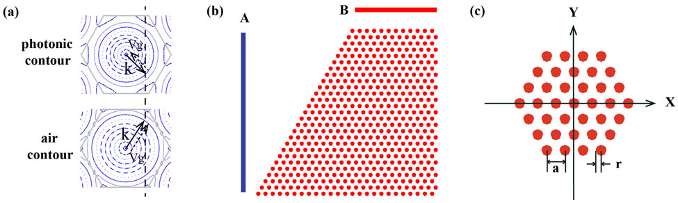
    Fig. 1. Configuration of the negative refractive PhC. (a) The principle of negative refraction. The direction of group velocity is along the increasing direction of the contour line. The wave vector is on the same side of the normal at the interface of the air and the PhC. (b) The two-dimensional PhC based on LN. Ports A and B are the two receivers to measure the transmission of the incident light. (c) The enlarged structure of the PhC with a hexagonal array. a is the lattice constant. r is the radius of the dielectric rod.
    Realization of the PBS. The incident light is separated after passing through the PhC. (a) TE polarization refracted in the negative direction. (b) TM polarization refracted in the positive direction. A and B are the two receivers to measure the light transmission.
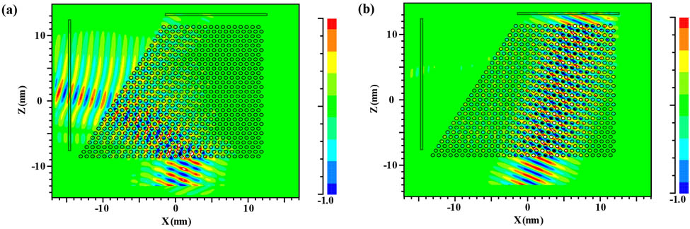
    Fig. 2. Realization of the PBS. The incident light is separated after passing through the PhC. (a) TE polarization refracted in the negative direction. (b) TM polarization refracted in the positive direction. A and B are the two receivers to measure the light transmission.
    Bandgap as a function of the wave vector for (a) TE polarization and (b) TM polarization.
    Fig. 3. Bandgap as a function of the wave vector for (a) TE polarization and (b) TM polarization.
    Curves of transmission versus free-space wavelength based on the normalizing condition with the incident angle of 20° of the two polarizations. (a) TE polarization. (b) TM polarization. The optional free-space wavelength range based on the normalizing condition is 1.85–1.92 μm. The normalized frequency range is 0.52–0.54.
    Fig. 4. Curves of transmission versus free-space wavelength based on the normalizing condition with the incident angle of 20° of the two polarizations. (a) TE polarization. (b) TM polarization. The optional free-space wavelength range based on the normalizing condition is 1.85–1.92 μm. The normalized frequency range is 0.52–0.54.
    Relationship between the transmission and incident angle. The gray segment represents the region where the PhC acts as a PBS. (a) TE polarization for LN-based PBS. (b) TE polarization for Si-based PBS. (c) TM polarization for LN-based PBS. (d) TM polarization for Si-based PBS. For the LN-based PBS, the angle bandwidth is 20°–28° with a light transmittance of over 80%. For the Si-based PBS, the transmission of TM polarization is less than 80%, due to the large reflection that occurs at the surface.
    Fig. 5. Relationship between the transmission and incident angle. The gray segment represents the region where the PhC acts as a PBS. (a) TE polarization for LN-based PBS. (b) TE polarization for Si-based PBS. (c) TM polarization for LN-based PBS. (d) TM polarization for Si-based PBS. For the LN-based PBS, the angle bandwidth is 20°–28° with a light transmittance of over 80%. For the Si-based PBS, the transmission of TM polarization is less than 80%, due to the large reflection that occurs at the surface.
    Relationship between the transmission and wavelength. The gray segment represents the region that the PhC acts as a PBS. (a) TE polarization for LN-based PBS. (b) TE polarization for Si-based PBS. (c) TM polarization for LN-based PBS. (d) TM polarization for Si-based PBS. The wavelength bandwidth range is 1.50–1.57 μm, and the span of the wavelength is 70 nm with a transmission of over 80% for the LN-based PBS. The transmission of TM polarization based on Si cannot be over 70% under the condition of the two polarizations separating completely, because it has much more energy because of the surface reflection.
    Fig. 6. Relationship between the transmission and wavelength. The gray segment represents the region that the PhC acts as a PBS. (a) TE polarization for LN-based PBS. (b) TE polarization for Si-based PBS. (c) TM polarization for LN-based PBS. (d) TM polarization for Si-based PBS. The wavelength bandwidth range is 1.50–1.57 μm, and the span of the wavelength is 70 nm with a transmission of over 80% for the LN-based PBS. The transmission of TM polarization based on Si cannot be over 70% under the condition of the two polarizations separating completely, because it has much more energy because of the surface reflection.
    Siqi Duan, Yuping Chen, Guangzhen Li, Chuanyi Zhu, Xianfeng Chen. Broadband polarization beam splitter based on a negative refractive lithium niobate photonic crystal slab[J]. Chinese Optics Letters, 2016, 14(4): 042301
    Download Citation