• Chinese Optics Letters
  • Vol. 14, Issue 8, 081301 (2016)
Xin Chen1、3, Chao Qiu2, Zhen Sheng1、2, Aimin Wu1、2、**, Haiyang Huang1、3, Yingxuan Zhao1, Wei Li1, Xi Wang1, Shichang Zou1, and Fuwan Gan1、2、*
Author Affiliations
  • 1State Key Laboratory of Functional Materials for Informatics, Shanghai Institute of Microsystem and Information Technology, Shanghai 200050, China
  • 2Nantong Opto-Electronics Engineering Center Chinese Academy of Science, Nantong 226000, China
  • 3University of Chinese Academy of Science, Beijing 100049, China
  • show less
    DOI: 10.3788/COL201614.081301 Cite this Article Set citation alerts
    Xin Chen, Chao Qiu, Zhen Sheng, Aimin Wu, Haiyang Huang, Yingxuan Zhao, Wei Li, Xi Wang, Shichang Zou, Fuwan Gan. Design of an ultra-broadband and fabrication-tolerant silicon polarization rotator splitter with SiO2 top cladding[J]. Chinese Optics Letters, 2016, 14(8): 081301 Copy Citation Text show less
    Schematic of the proposed device based on a cascaded adiabatic bi-level taper and mode-evolution counter-tapered coupler.
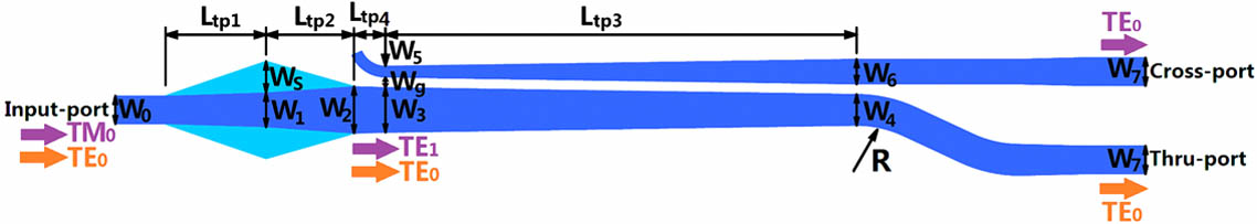
    Fig. 1. Schematic of the proposed device based on a cascaded adiabatic bi-level taper and mode-evolution counter-tapered coupler.
    (a) The calculated effective refractive indices of the first three modes in the waveguide cross section along the bi-level taper at wavelengths of 1310 nm (dashed) and 1550 nm (straight). (b) The electric field profiles of the first two modes in the cross section along this taper at the wavelength of 1310 nm.
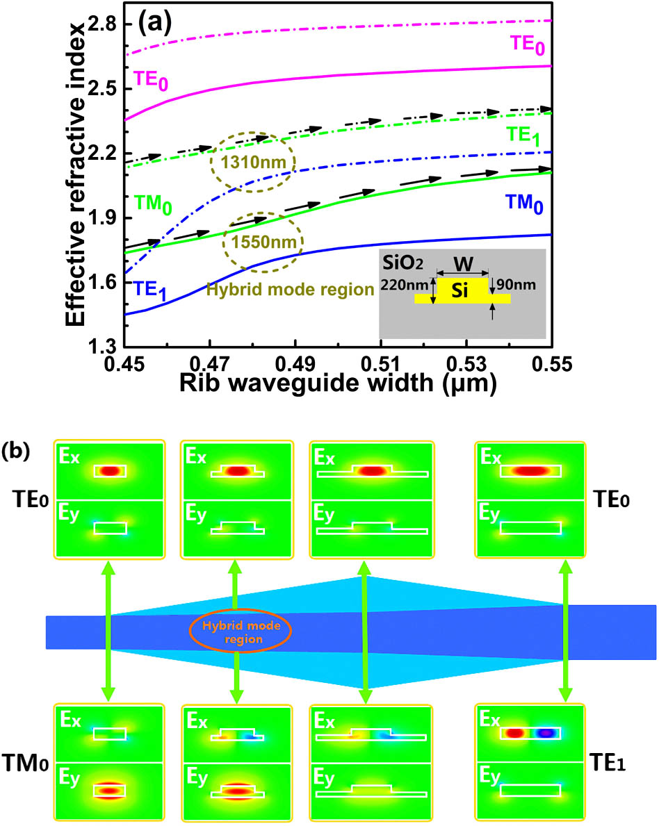
    Fig. 2. (a) The calculated effective refractive indices of the first three modes in the waveguide cross section along the bi-level taper at wavelengths of 1310 nm (dashed) and 1550 nm (straight). (b) The electric field profiles of the first two modes in the cross section along this taper at the wavelength of 1310 nm.
    (a) The mode conversion efficiency from the TM0 mode to TE1 mode in the bi-level taper as the Ltp1 varies with the second taper length Ltp2=15, 20, and 25 μm at the wavelength of 1310 nm (dashed) and 1550 nm (straight). (b) Wavelength dependence of the mode conversion efficiency when Ltp1=28.5 μm and Ltp2=25 μm. Inset: simulated electric field intensity distributions in the bi-level taper as the TM0 mode launched at 1310 and 1550 nm wavelengths.
    Fig. 3. (a) The mode conversion efficiency from the TM0 mode to TE1 mode in the bi-level taper as the Ltp1 varies with the second taper length Ltp2=15, 20, and 25 μm at the wavelength of 1310 nm (dashed) and 1550 nm (straight). (b) Wavelength dependence of the mode conversion efficiency when Ltp1=28.5μm and Ltp2=25μm. Inset: simulated electric field intensity distributions in the bi-level taper as the TM0 mode launched at 1310 and 1550 nm wavelengths.
    (a) The calculated effective refractive indices of the modes (TE0/TE0 and TE1) in the cross/through waveguide of the counter-tapered coupler with width tapering from 0.18/0.72 to 0.4/0.5 μm at wavelengths of 1310 nm (dashed) and 1550 nm (straight). (b) Mode conversion loss from the launched TE1 mode to the TE0 mode at the wavelengths of 1310 and 1550 nm. Inset: wavelength dependence of the mode conversion loss at Ltp3=200 μm and Wg=0.16 μm. (c) and (d) Simulated electric field intensity distributions in the counter-tapered coupler as the TE1 mode launched at the wavelengths of 1310 and 1550 nm, respectively. W7=0.45 μm.
    Fig. 4. (a) The calculated effective refractive indices of the modes (TE0/TE0 and TE1) in the cross/through waveguide of the counter-tapered coupler with width tapering from 0.18/0.72 to 0.4/0.5 μm at wavelengths of 1310 nm (dashed) and 1550 nm (straight). (b) Mode conversion loss from the launched TE1 mode to the TE0 mode at the wavelengths of 1310 and 1550 nm. Inset: wavelength dependence of the mode conversion loss at Ltp3=200μm and Wg=0.16μm. (c) and (d) Simulated electric field intensity distributions in the counter-tapered coupler as the TE1 mode launched at the wavelengths of 1310 and 1550 nm, respectively. W7=0.45μm.
    (a) Wavelength dependence of the PRS performance in terms of the IL and CT for different launched modes. (b)–(g) Simulated electric field intensity distributions in our proposed PRS as the TE0 mode and TM0 mode launched at the wavelengths of 1310, 1490, and 1550 nm.
    Fig. 5. (a) Wavelength dependence of the PRS performance in terms of the IL and CT for different launched modes. (b)–(g) Simulated electric field intensity distributions in our proposed PRS as the TE0 mode and TM0 mode launched at the wavelengths of 1310, 1490, and 1550 nm.
    Fabrication tolerance analysis for the wavelength dependence of IL and CT with (a) the top silicon thickness variation ΔH, (b) the slab height variation Δh, and (c) the waveguide width variation ΔW of the whole device as the TM0 mode launched.
    Fig. 6. Fabrication tolerance analysis for the wavelength dependence of IL and CT with (a) the top silicon thickness variation ΔH, (b) the slab height variation Δh, and (c) the waveguide width variation ΔW of the whole device as the TM0 mode launched.
    ParametersValues (μm)ParametersValues (μm)
    W00.45Ws0.5
    W10.55Wg0.16
    W20.75Ltp128.5
    W30.72Ltp225
    W40.5Ltp3200
    W50.18Ltp410
    W60.4R20
    W70.45
    Table 1. Parameters and Corresponding Values of the Proposed Device
    Xin Chen, Chao Qiu, Zhen Sheng, Aimin Wu, Haiyang Huang, Yingxuan Zhao, Wei Li, Xi Wang, Shichang Zou, Fuwan Gan. Design of an ultra-broadband and fabrication-tolerant silicon polarization rotator splitter with SiO2 top cladding[J]. Chinese Optics Letters, 2016, 14(8): 081301
    Download Citation