
J. Schreiber, F. Bell, and Z. Najmudin. Optimization of relativistic laser–ion acceleration[J]. High Power Laser Science and Engineering, 2014, 2(4): 04000e41
- High Power Laser Science and Engineering
- Vol. 2, Issue 4, 04000e41 (2014)
Abstract
1. Introduction
Laser-driven ion acceleration has created enormous interest over the last few years[ has enabled the generation of multi-MeV ion beams with exceptional characteristics[
The observation of ions emitted in laser–plasma interactions can first be traced to experiments employing high-intensity laser pulses with durations of a few ns to some hundreds of ps[ and fs durations were realized. The new era of relativistic laser–plasma interactions had begun, where the quiver velocity of electrons in the electromagnetic field of the laser approaches the speed of light. Moreover, the
  -term of the Lorentz force becomes dominant and pushes the electrons into the direction of laser propagation. The generation of relativistic electrons was the fundamental requisite for the acceleration of ions to high energy[
Although a number of high-power, PW-class laser systems have been built around the world, the early record energy of 60 MeV[
Sign up for High Power Laser Science and Engineering TOC. Get the latest issue of High Power Laser Science and Engineering delivered right to you!Sign up now
2. Target normal sheath acceleration
TNSA of ions has been extensively investigated over the last decade. In fact, until now it has proved to be the most effective method for ion acceleration when highly intense laser pulses are focused onto foils with thicknesses of several micrometers. TNSA relies on the efficient conversion of laser energy into hot, relativistic electrons. These electrons propagate through the target and set up fields at the target boundaries where they exit into vacuum. The electric field is created between the expelled electrons and the surface charge that they induce on the target. Since the electric field strength is of the same relative strength as the laser electric field amplitude (TV/m) which generates the hot electrons, most of the electrons return back into the target. Hence an electron cloud (sheath) is formed. Ions at the rear surface can be accelerated by the sheath fields to multi-MeV energies in only several tens of femtoseconds. Impurities such as hydrocarbon and water are present under most experimental conditions at the solid surface. Due to their higher charge-to-mass ratio, it is the protons from these contaminants that are most readily accelerated to high energies. However, by removing the contaminants by different means, the acceleration of heavier ions can also be optimized[
A large number of experimental results on laser-driven ion acceleration are now available[
2.1. Nonrelativistic TNSA
The original Schreiber model[ into those electrons and the transverse size of the electron cloud
  . (ii) Due to the consideration of the transverse dimension
  of the electron cloud when it exits the rear of the target, the resultant potential stays finite which is in contrast to most 1D models, where for infinite acceleration times the ion energies diverge[
 electrons with an average energy
  in a bunch of length
  , where
  is the laser pulse duration and the electrons are assumed to propagate with the speed of light
  . On their way through the target, the electrons spread over a circular region with radius
  . When exiting into vacuum a positive surface charge
  is induced at the rear side of the target which yields a returning force
  . Electrons run up the potential and eventually reverse their path at a distance
  above the surface of the foil and re-enter the foil. In an equilibrium situation
  electrons are permanently outside the foil. To achieve global charge neutrality we identify this number with the number of positive surface charges
  . The potential of the corresponding charge density is
 (1)
(1)In the following we will concentrate on the center of the acceleration region that is responsible for the most energetic ions, i.e.,  . In that case the integration of Equation (
 (2)
(2) (3)
(3) . For short distances
  one has
  , which yields for the turning point
  . The total number of electrons is related to the laser energy
  by
by  where
where  is the efficiency by which the laser energy is converted into electron energy. The electrons are provided for the duration of the laser pulse
  . With
  (the power of the laser pulse) we obtain the potential barrier
  (4)
(4) because
  . The essential point is that laser energy is mainly converted into a large number of energetic electrons (fast enough to traverse the target) which in turn build up a dense electron sheath exhibiting extraordinary strong electric fields. It is thus not decisive what average energies
  are gained by the laser. This is in contrast to the model proposed by Bulanov
  an ion with charge
  gains between
  (the surface) and
  :
:  (5)
(5) (6)
(6) (7)
(7) . Since
 (8)
(8) (9)
(9) and
and  . Finally, the integration yields
 (10)
(10) , where
  is the normalized maximum ion energy and
  defines the normalized energy an ion could gain from the potential of the sheath if it were maintained stationary, and is given by
  . Here,
  and
and  are the laser pulse duration and energy respectively,
  is the ion charge state,
  is the nucleon number of the target,
  is the relativistic power unit (
 ,
,  ) and
) and  is the absorption efficiency into hot electrons. Following Refs. [
 , where
  is in units of
  , up to a maximum
  . This scaling has been validated for a laser wavelength of
  and pulse durations of several hundreds of femtoseconds. We mention that a similar model has been developed by Bulanov
  positive charges. The corresponding potential is given by Landau and Lifshitz[
 have to vanish, which can only be fulfilled by a specific distribution of the
  charges at the surface. However, that can be in contradiction to the laser-driven charge distribution of hot electrons which might be very different from any ‘conducting’ equilibrium.
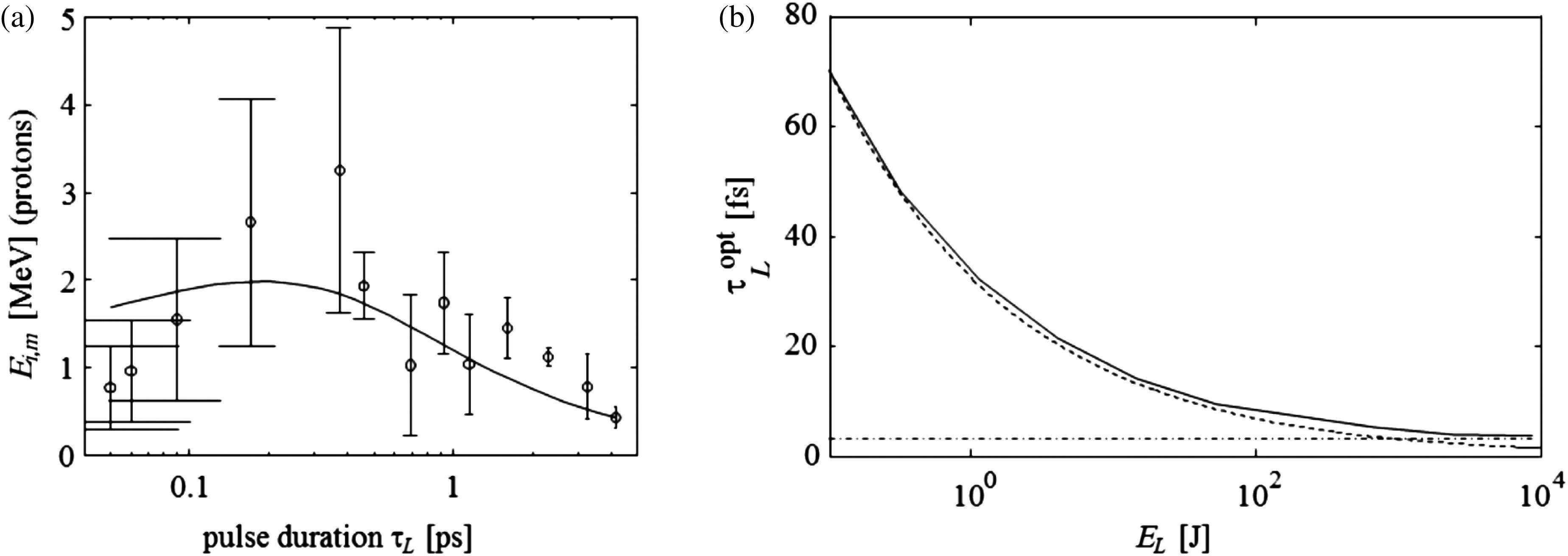
One major result of the model presented is that for a given laser energy  , the shortest laser pulses and thus highest intensities are not necessarily optimal for TNSA. An important point is that the normalized maximum energy
  an ion can gain depends on the pulse duration
  which has a strong consequence on the maximal ion energy
  . This can be seen in Figure
  (Ref. [
 as a function of the laser pulse duration
  , showing explicitly that there exists an optimal duration
  . This behavior has been verified on other laser systems as well[
 . The solid curve in Figure
  . For the nonrelativistic solution, Equation (
 (11)
(11) is evaluated at
  . Insertion of Equations (
 with the corresponding value for
  . On inserting the nonrelativistic characteristic time
  , one obtains for the optimum pulse duration
  (12)
(12) ,
,  and
and  . The dashed line is the nonrelativistic solution of Equation (
 (13)
(13) is the relativistic power unit for a proton. From Equation (
 should be minimized in order to obtain the largest maximum ion energy
  . This is realized for the smallest possible source size
  , where
  is the radius of the beam spot. Therefore, it is convenient to use targets with thickness
  much smaller than the radius of the focal spot, which is usually of the order of some micrometers.
2.2. Relativistic TNSA
The relativistic equation of motion is
 (14)
(14) (15)
(15) and
and  , as before. The resulting two coupled first-order differential equations
  (16)
(16) (17)
(17) and
and  . The initial condition is
  ,
,  and
and  . The ion energy is given by
  with
with  . A first integration of Equation (
 (18)
(18) (19)
(19) (20)
(20) (21)
(21) and
and  . It is immediately seen from Equation (
 (compare Equation (
 might become arbitrarily large, but special relativity limits it to the speed of light. We note that Equation (
 (22)
(22) (23)
(23) the additional parameter
  accounts for relativistic effects. Using the value of
  of the nonrelativistic TNSA expression as a first-order solution we obtain a condition for the optimized pulse duration in the case of relativistic TNSA:
 (24)
(24) (25)
(25) . An analytic solution of Equation (
 (26)
(26) and
and  . The nonrelativistic TNSA-limit Equation (
 :
:  (27)
(27) is obtained by Equation (
 . This can be expected. However, (2) the correction decreases the value of
  ; in other words, the optimum pulse duration
  is reduced even when the laser energy
  remains constant. This in turn means that the optimum ion energy becomes larger if relativistic corrections are taken into account. (3) The correction increases with increasing
  . Nonrelativistically
  increases with
  (see Equation (
Writing Equation (
 (28)
(28) yields
 (29)
(29) (30)
(30) (31)
(31) (32)
(32) and
and 
 . A numerical solution yields
  with
with  as a parameter. By inserting these solutions into Equation (
 (solid line in Figure
  .
.In the highly relativistic regime, the ion velocity approaches the speed of light for approximately all the acceleration time, which according to Equation (
 (33)
(33) (34)
(34) (35)
(35) has a rather broad maximum at
  . Whereas in the nonrelativistic regime the optimum pulse duration decreases with increasing laser energy
  , see Equation (
 , for relativistic ion energies (dash-dotted line in Figure
  one obtains from Equation (
 (36)
(36) is a unique function of
  and
and  , i.e., for constant laser energy a function of
  only. Thus,
  might show a maximum with respect to
  or not. However, if there exists a maximum it is unique, i.e., there is a single-valued
  only. (ii) We propose a simple equation for the whole range,
  (37)
(37) (38)
(38) is replaced by
  . Bulanov
  ), they obtained for
  and a pulse duration of
  (i.e., a laser energy of
  ) a proton energy of 1.3 GeV. With
  and
and  we obtain from Equation (
 .
.3. Radiation pressure acceleration
At the intensities available with present high-intensity lasers, it seems natural to consider RPA as a means of accelerating objects to high energy. RPA offers the most promising approach for the acceleration of plasma bunches with near-solid, or at least overcritical, density to relativistic velocities. The principle of RPA is the same as was proposed to use continuous wave lasers to drive interstellar vehicles to relativistic velocities[ , this would require only 5 J of energy. Unfortunately, the picture is not quite as simple due to the immense intensity of the applied laser. In Section
The acceleration of an object with mass  by the radiation pressure, where
  is the ion particle density, is described by Refs. [
 (39)
(39) and
and  denotes the reflectivity with which the laser is reflected. For a constant laser power
  , a solution of Equation (
 is not of much interest because of the retardation effect. More relevant is a solution in terms of the retarded time
  (Refs. [
 (40)
(40) (41)
(41) , since the light pulse is terminated at the retarded time
  . We note that the interaction between the light and the plasma sheet may continue even when the laser has finished radiating: for relativistic velocities of the sheet the light pulse accompanies the bunch for interaction times
  much longer than the pulse duration
  (42)
(42) is accelerated cooperatively as a charge-neutral plasma bunch. The physical mechanism behind this process is the following. Due to their small mass the electrons are accelerated by light pressure and then due to Coulomb forces drag the ions behind them (hence the name light-sail[
On inspecting Equation ( increases with
  and thus with decreasing target mass
  , or with thinner target foils. However, a lower limit will be reached if the number of ions becomes so small that they cannot any longer retain the electrons by their Coulomb forces. One estimates the energy
  to separate an electron from a sheet of ion charge density
  to be
to be  (Ref. [
 while the radiation pressure decreases like
  , advocating once more the use of ultra-thin targets. The ion energy can be derived from Equation (
 . For a completely ionized carbon target with a thickness of
  one obtains
  . On the other hand, this estimate shows that there exists a lower limit on the electron mass
  that can be accelerated by radiation pressure and which remains bound to the ions. The latter demand is essential for ion acceleration since it is the electrons that pull the ions behind them. If
  becomes too small, the resulting fast electrons with energies
  (note that at large electron energies the efficiency approaches 100%, i.e., all the laser energy is converted into the kinetic energy of
  electrons) can surmount the potential barrier built up by the charge separation field (note that
  ). Thus, the minimum ion mass that prohibits charge separation and that can be accelerated as a charge-neutral plasma bunch becomes
 (43)
(43) and
and  the mass number of the target. For a carbon target with
  ,
,  and
and  one obtains
  , corresponding to an optimum thickness of 4 nm. This is in strong contrast to a TNSA model of Andreev
  . As expected, the ion energy increases with
  , but for masses close to
  the energy starts to drop rather strongly with further decreasing target masses, thus confirming the estimate of Equation (
In a very recent theory of laser ion acceleration from thin foils[
 (44)
(44) and thus
  prohibits charge separation, i.e., allows collective ion acceleration induced by electrons riding ahead of the ions. Here,
  is the critical electron density. It is easy to show that Equation (
 with
with  of Equation (
 for an appropriate ion acceleration is equivalent to demanding
  . Identifying
  with the optimal target mass
  for RPA and inserting Equations (
 , which can be compared with the equivalent expression for the case of optimal TNSA. In Figure
  has been plotted for either TNSA or RPA versus the laser energy
  . The curves hold for
  (solid lines) and
  (dashed lines),
  and
and  . For a typical high-intensity laser with a wavelength of
  , a beam spot radius of
  is close to the diffraction-limited minimum sized beam spot. The corresponding data in Figure
  could accelerate by radiation pressure a carbon foil of optimal thickness of
  with C ions in it up to energies of 60 TeV/ion (
 , which is close to the heavy-ion energies of CERN’s Large Hadron Collider[
 , see also Equation (
 and one by pair production of
  . Energy losses due to bremsstrahlung can be neglected since the small impact parameters necessary to generate hard photon quanta lead unavoidably to a fragmentation of the projectile[
 compared with
  protons stored within 27 km. The corresponding pulse length of
  is long enough to allow kicker magnets to sweep the beam across the absorber.
It is readily seen that except for a minor factor over the whole range of laser energies both optimized theories yield the same maximum ion energies. It is therefore more a question of practicability what kind of optimization one chooses,  or
or  . There might exist technical limits: it is certainly very difficult to obtain pulse durations shorter than say 1 fs. According to Equation (
 , which in essence does not pose a strong limit. On the other hand, in the case of RPA a lower limit of
  is reached for a monolayer of atoms. Assuming a carbon foil as the target (the most popular choice) one obtains a lower limit of
  , or from Equation (
 , which also does not have a practical influence. We emphasize that the optimizing procedure developed in this paper only works since the TNSA theory of Schreiber
In addition, experimental results are plotted in Figure  or
or  , i.e., relativistic energies, are obtained for laser energies
  only and so far have only been obtained in PIC simulations. Finally, we note that the efficiency of RPA can be written as
 (45)
(45) or with Equation (
 one obtains that for
  , 100% of the laser energy is converted into ion energy.
Of course, if the transverse light intensity changes, different parts of the sail will be accelerated differently changing an initially plane sail to a convex one. The equation of motion of Equation (
 (46)
(46) and the unit vector
  of the sail’s surface normal depend on the transverse coordinates
  and time
  . Thus, a solution of Equation (
 and the shape of the sail, allowing for bowing while simultaneously submitting it to the condition of constant mass, has been given in Ref. [
4. Discussion
We are very much aware that analytic descriptions of the complex laser-assisted acceleration process of ions are hampered in many aspects. In contrast, PIC simulations describe in much more detail the complex processes described here. However, we also believe that an analytic description of the multi-parameter behavior of the process and its interdependences can give a more general overlook of the strategy to obtain the required outcomes such as, e.g., maximum ion energies. At the same time we remark that also PIC simulations which in essence are based on a mean field theory may rather severely suppress microscopic interactions. We also recognize a significant overshoot of PIC simulations, promising ion beams of great quality not verified by experiment hitherto. We cite a very recent paper: ‘as pointed out recently in a number of papers circular polarized laser pulses can accelerate ions very efficiently and produce sharply peaked spectra’[
We note that such high energies as predicted by the analytical models have not been observed yet even though comparable laser conditions have been applied, for example by Mackinnon  , even though the target thickness
  was smaller than
  in those experiments.
Hence, the studies presented here are encouraging in view of future applications that rely on high-repetition-rate laser systems. For example, for medical applications such as ion tumor therapy energies exceeding 100 MeV/u are envisioned. This energy range should be attainable even with sub-100 J laser systems, while relativistic energies can be achieved with energies slightly above 100 J. In order to increase the ion energy even further, i.e., above the multi-GeV level, kJ systems such as envisioned for the Extreme Light Infrastructure will be necessary. It may also become necessary to consider novel methods not discussed here. For example, once the ions move with the speed of light, staged acceleration possibly implementing plasma wake acceleration as used presently to accelerate electrons may provide a more effective means to reach higher energies[
5. Summary
Starting from experimental results, we have shown that current theories of laser–ion acceleration can and should be optimized in order to achieve maximum ion energies. Not all theories include such a possibility, but the TNSA theory of Schreiber  . It is thus a matter of convenience whether one adjusts the optimal pulse duration or the optimal target thickness. For both theories, the decisive laser parameter is neither the power nor the intensity but solely the laser energy. Relativistic ion energies, i.e., energies beyond 1 GeV/u, can be obtained for systems with
  , where in addition a diffraction-limited small spot size has to be achieved.
References
[1] H. Daido, M. Nishiuchi, A. S. Pirozhkov. Rep. Progr. Phys., 75(2012).
[2] A. Macchi, M. Borghesi, M. Passoni. Rev. Modern Phys., 85, 751(2013).
[5] T. Tajima, M. Kando, M. Teshima. Progr. Theoret. Phys., 125, 617(2011).
[13] S. V. Bulanov, V. S. Khoroshkov. Plasma Phys. Rep., 28, 453(2002).
[14] E. Fourkal, B. Shahine, M. Ding, J. S. Li, T. Tajima, C. M. Ma. Med. Phys., 29, 2788(2002).
[17] U. Linz, J. Alonso. Phys. Rev. ST Accel. Beams, 10(2007).
[27] D. Strickland, G. Morou. Opt. Commun., 56, 219(1985).
[31] J. F. L. Simmons, C. R. McInnes. Amer. J. Phys., 61, 205(1993).
[33] W. Yu, H. Xu, F. He, M. Y. Yu, S. Ishiguro, J. Zhang, A. Y. Wong. Phys. Rev. E, 72(2005).
[34] A. Macchi, F. Cattani, T. V. Liseykina, F. Cornolti. Phys. Rev. Lett., 94(2005).
[35] T. Esirkepov, M. Borghesi, S. V. Bulanov, G. Mourou, T. Tajima. Phys. Rev. Lett., 92(2004).
[36] X. Zhang, B. Shen, X. Li, Z. Jin, F. Wang, M. Wen. Phys. Plasmas, 14(2007).
[37] A. Robinson, M. Zepf, S. Kar, R. Evans, C. Bellei. New J. Phys., 10(2008).
[38] O. Klimo, J. Psikal, J. Limpouch, V. T. Tikhonchuk. Phys. Rev. ST Accel. Beams, 11(2008).
[39] X. Q. Yan, C. Lin, Z. M. Sheng, Z. Y. Guo, B. C. Liu, Y. R. Lu, J. X. Fang, J. E. Chen. Phys. Rev. Lett., 100(2008).
[40] B. Qiao, S. Kar, M. Geissler, P. Gibbon, M. Zepf, M. Borghesi. Phys. Rev. Lett., 108(2012).
[41] B. Shen, Z. Xu. Phys. Rev. E, 64(2001).
[42] B. Qiao, M. Zepf, M. Borghesi, M. Geissler. Phys. Rev. Lett., 102(2009).
[43] A. Macchi, S. Veghini, F. Pegoraro. Phys. Rev. Lett., 103(2009).
[44] B. Qiao, M. Zepf, P. Gibbon, M. Borghesi, J. Schreiber, M. Geissler. Proc. SPIE, 8079(2011).
[45] P. Lebedew. Ann. Phys., 311, 433(1901).
[46] E. F. Nichols, G. F. Hull. Astrophys. J., 17, 315(1903).
[47] F. A. Zander. Tech. Zhizn, 13, 15(1924).
[48] A. S. Eddington. Mon. Not. R. Astron. Soc., 85, 408(1925).
[49] V. I. Veksler. Sov. J. At. Energy, 2, 525(1957).
[50] G. Marx. Nature, 211, 22(1966).
[51] A. Henig, S. Steinke, M. Schnürer, T. Sokollik, R. Hörlein, D. Kiefer, D. Jung, J. Schreiber, B. M. Hegelich, X. Q. Yan, J. Meyer-ter-Vehn, T. Tajima, P. V. Nickles, W. Sandner, D. Habs. Phys. Rev. Lett., 103(2009).
[55] A. Henig, D. Kiefer, K. Markey, D. C. Gautier, K. A. Flippo, S. Letzring, R. P. Johnson, T. Shimada, L. Yin, B. J. Albright, K. J. Bowers, J. C. Fernández, S. G. Rykovanov, H.-C. Wu, M. Zepf, D. Jung, V. Kh. Liechtenstein, J. Schreiber, D. Habs, B. M. Hegelich. Phys. Rev. Lett., 103(2009).
[65] T. Fujii, Y. Oishi, T. Nayuki, Y. Takizawa. Appl. Phys. Lett., 83, 1524(2003).
[69] D. Jung, L. Yin, B. J. Albright, D. C. Gautier, S. Letzring, B. Dromey, M. Yeung, R. Hörlein, R. Shah, S. Palaniyappan. New J. Phys., 15(2013).
[70] D. Jung, L. Yin, D. C. Gautier, H.-C. Wu, S. Letzring, B. Dromey, R. Shah, S. Palaniyappan, T. Shimada, R. P. Johnson, J. Schreiber, D. Habs, J. C. Fernández, B. M. Hegelich, B. J. Albright. Phys. Plasmas, 20(2013).
[71] A. Pukhov. Phys. Rev. Lett., 86, 3562(2001).
[72] Q. L. Dong, Z. M. Sheng, M. Y. Yu, J. Zhang. Phys. Rev. E, 68(2003).
[73] T. Esirkepov, M. Yamagiwa, T. Tajima. Phys. Rev. Lett., 96(2006).
[74] L. Yin, B. J. Albright, B. M. Hegelich, K. J. Bowers, K. A. Flippo, T. J. T. Kwan, J. C. Fernández. Phys. Plasmas, 14(2007).
[75] X. Q. Yan, H. C. Wu, Z. M. Sheng, J. E. Chen, J. Meyer-ter-Vehn. Phys. Rev. Lett., 103(2009).
[77] M. Passoni, M. Lontano. Laser Part. Beams, 22, 163(2004).
[78] M. Lontano, M. Passoni. Phys. Plasmas, 13(2006).
[79] A. P. Robinson, A. R. Bell, R. J. Kingham. Phys. Rev. Lett., 96(2006).
[80] M. M. Basko. Eur. Phys. J. D, 41, 641(2007).
[81] M. Passoni, M. Lontano. Phys. Rev. Lett., 101(2008).
[82] A. V. Brantov, V. T. Tikhonchuk, V. Y. Bychenkov, S. G. Bochkarev. Phys. Plasmas, 16(2009).
[83] G. A. Mourou, T. Tajima, S. V. Bulanov. Rev. Modern Phys., 78, 309(2006).
[84] P. Mora. Phys. Rev. Lett., 90(2003).
[85] S. S. Bulanov, V. Yu. Bychenkov, V. Chvykov, G. Kalinchenko, D. W. Litzenberg, T. Matsuoka, A. G. R. Thomas, L. Willingale, V. Yanovsky, K. Krushelnick, A. Maksimchuk. Phys. Plasmas, 17(2010).
[86] J. Yu, Z. Jiang, J. C. Kieffer, A. Krol. Phys. Plasmas, 6, 1318(1999).
[88] L. D. Landau, J. S. Bell, M. J. Kearsley, L. P. Pitaevskii, E. M. Lifshitz, J. B. Sykes. Electrodynamics of Continuous Media, 8(1984).
[91] J. Meyer-ter-Vehn, H.-C. Wu. Eur. Phys. J. D, 55, 433(2009).
[92] F. Pegoraro, S. V. Bulanov. Eur. Phys. J. D, 55, 399(2009).
[95] M. Chen, A. Pukhov, T. P. Yu, Z. M. Sheng. Phys. Rev. Lett., 103(2009).
[96] X. Q. Yan, T. Tajima, M. Hegelich, L. Yin, D. Habs. Appl. Phys. B, 98, 711(2010).
[97] A. H. Sørensen. Phys. Rev. A, 81(2010).
[98] T.?L.?S. Group,.
[99] H.-C. Wu, T. Tajima, D. Habs, A. W. Chao, J. Meyer-ter-Vehn. Phys. Rev. ST Accel. Beams, 13(2010).
[100] A. Ferrari, G. R. Stevenson, E. Weisse. Proceedings of 3rd European Particle Accelerator Conference 1545(1992).
[102] F. Pegoraro, S. V. Bulanov, J. I. Sakai, G. Tomassini. Phys. Rev. E, 64(2001).
[103] S. V. Bulanov, E. Y. Echkina, T. Z. Esirkepov, I. N. Inovenkov, M. Kando, F. Pegoraro, G. Korn. Phys. Plasmas, 17(2010).
[105] F. Pegoraro, S. V. Bulanov. Phys. Rev. Lett., 99(2007).
[106] S. C. Wilks, W. L. Kruer, M. Tabak, A. B. Langdon. Phys. Rev. Lett., 69, 1383(1992).
[109] B. Shen, X. Zhang, Z. Sheng, M. Y. Yu, J. Cary. Phys. Rev. ST Accel. Beams, 12(2009).
[110] X. Zhang, B. Shen, L. Ji, F. Wang, M. Wen, W. Wang, J. Xu, Y. Yu. Phys. Plasmas, 17(2010).
[111] F. L. Zheng, S. Z. Wu, H. C. Wu, C. T. Zhou, H. B. Cai, M. Y. Yu, T. Tajima, X. Q. Yan, X. T. He. Phys. Plasmas, 20(2013).
[114] I. J. Kim, K. H. Pae, C. M. Kim, H. T. Kim, J. H. Sung, S. K. Lee, T. J. Yu, I. W. Choi, C.-L. Lee, K. H. Nam, P. V. Nickles, T. M. Jeong, J. Lee. Phys. Rev. Lett., 111(2013).
[116] D. JungIon acceleration from relativistic laser nano-target interaction.
[117] H. Y. Wang, C. Lin, F. L. Zheng, Y. R. Lu, Z. Y. Guo, X. T. He, J. E. Chen, X. Q. Yan. Phys. Plasmas, 18(2011).
[118] A. Sgattoni, S. Sinigardi, A. Macchi. Appl. Phys. Lett., 105(2014).

Set citation alerts for the article
Please enter your email address
© Copyright 2018-2021 | Chinese Laser Press. All Rights Reserved 沪ICP备15018463号-20