• Photonics Research
  • Vol. 8, Issue 7, 1177 (2020)
Shanshan Chen1、†, Wei Wei2、†, Zhiguang Liu3, Xing Liu1, Shuai Feng2, Honglian Guo2、4、*, and Jiafang Li1、3、5、*
Author Affiliations
  • 1Key Laboratory of Advanced Optoelectronic Quantum Architecture and Measurement (Ministry of Education), Beijing Key Laboratory of Nanophotonics & Ultrafine Optoelectronic Systems, and School of Physics, Beijing Institute of Technology, Beijing 100081, China
  • 2School of Science, Minzu University of China, Beijing 100081, China
  • 3Institute of Physics, Chinese Academy of Sciences, Beijing 100190, China
  • 4e-mail: hlguo@muc.edu.cn
  • 5e-mail: jiafangli@bit.edu.cn
  • show less
    DOI: 10.1364/PRJ.393333 Cite this Article Set citation alerts
    Shanshan Chen, Wei Wei, Zhiguang Liu, Xing Liu, Shuai Feng, Honglian Guo, Jiafang Li. Reconfigurable nano-kirigami metasurfaces by pneumatic pressure[J]. Photonics Research, 2020, 8(7): 1177 Copy Citation Text show less
    (a) (I) Perspective view, top-view, and side-view schematic diagrams of a chamber for the pneumatic reconfiguration of metasurfaces (the yellow structure). One end of the chamber is inflated with nitrogen and the other end is connected to a barometer to measure the pneumatic pressure applied on the samples. (II) Schematic illustration of the fabrication process. (b) Top-view schematic of the unit cells consisting of (left) the reported single MEMS deformable spiral for terahertz polarization modulation [26], and (right) the proposed combined four Archimedean spirals in this work. Each spiral contains two 90° arcs with radius r(1) and r(2), respectively, and is rotated around the unit center (noted by the central red dot). The size of the combined spiral is reduced by two orders of magnitude and the stability is enhanced by its four legs connected with the master film. (c) and (d) Schematic illustrations of the proposed reconfigurable Au/SiN bilayer metasurfaces under pneumatic forces: (c) initial 2D porous spirals in a square lattice and (d) corresponding deformed 3D spirals under pneumatic pressure.
    Fig. 1. (a) (I) Perspective view, top-view, and side-view schematic diagrams of a chamber for the pneumatic reconfiguration of metasurfaces (the yellow structure). One end of the chamber is inflated with nitrogen and the other end is connected to a barometer to measure the pneumatic pressure applied on the samples. (II) Schematic illustration of the fabrication process. (b) Top-view schematic of the unit cells consisting of (left) the reported single MEMS deformable spiral for terahertz polarization modulation [26], and (right) the proposed combined four Archimedean spirals in this work. Each spiral contains two 90° arcs with radius r(1) and r(2), respectively, and is rotated around the unit center (noted by the central red dot). The size of the combined spiral is reduced by two orders of magnitude and the stability is enhanced by its four legs connected with the master film. (c) and (d) Schematic illustrations of the proposed reconfigurable Au/SiN bilayer metasurfaces under pneumatic forces: (c) initial 2D porous spirals in a square lattice and (d) corresponding deformed 3D spirals under pneumatic pressure.
    (a) Schematics of the spiral unit cell and (b) the simulated 3D deformed counterpart with a deformation height of 130 nm. The violet lines in the left-side image of (a) denote the top-view outlines of the deformed spirals in (b). The right-side image of (b) shows the degree of the vertical deformation. Each spiral contains two 90° arcs with radii of 350 and 525 nm, respectively. (c) Calculated (Cal) and experimental (Exp) reflection spectra of the 2D porous metasurface. (d) (left) Calculated reflection spectrum of the deformed metasurface under a vertical deformation of 130 nm and (right) corresponding modification contrast in reflection (ΔR/R) versus wavelength. The reflection spectral dip shifts from 2076 to 1986 nm with a dramatic modification of 181% at wavelength 2100 nm. (e) Top-view and side-view simulated (left) E-field distributions (|E|) and (right) their vertical component (Ez) for the 2D and 3D spirals at wavelength 2076 nm. The left and right scale bars correspond to the field of |E| and Ez, respectively.
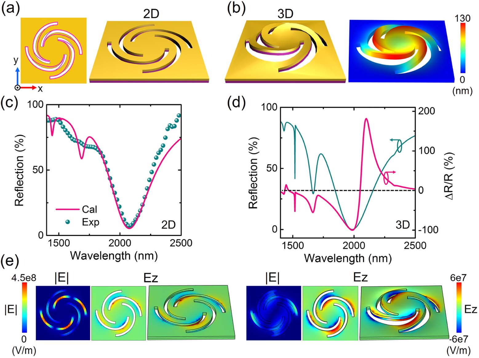
    Fig. 2. (a) Schematics of the spiral unit cell and (b) the simulated 3D deformed counterpart with a deformation height of 130 nm. The violet lines in the left-side image of (a) denote the top-view outlines of the deformed spirals in (b). The right-side image of (b) shows the degree of the vertical deformation. Each spiral contains two 90° arcs with radii of 350 and 525 nm, respectively. (c) Calculated (Cal) and experimental (Exp) reflection spectra of the 2D porous metasurface. (d) (left) Calculated reflection spectrum of the deformed metasurface under a vertical deformation of 130 nm and (right) corresponding modification contrast in reflection (ΔR/R) versus wavelength. The reflection spectral dip shifts from 2076 to 1986 nm with a dramatic modification of 181% at wavelength 2100 nm. (e) Top-view and side-view simulated (left) E-field distributions (|E|) and (right) their vertical component (Ez) for the 2D and 3D spirals at wavelength 2076 nm. The left and right scale bars correspond to the field of |E| and Ez, respectively.
    (a) Top-view and side-view SEM images of a single spiral fabricated by FIB. (b) and (c) Top-view SEM images of the fabricated spirals in a square lattice. The overall size is 40 μm×40 μm, with a periodicity of 1.5 μm. (d) and (e) Side-view SEM images of (d) 2D spirals and (e) the deformed 3D spirals by FIB-based nano-kirigami. (f) (left) Measured reflection spectra of the fabricated 2D spirals and deformed 3D spirals. (right) Corresponding modification contrast in reflection versus wavelength. The reflection spectral dip shifts from 2077 to 1989 nm with a significant modification of 137% at wavelength 2090 nm. Scale bars of (a), (b), (d), and (e) are 1 μm.
    Fig. 3. (a) Top-view and side-view SEM images of a single spiral fabricated by FIB. (b) and (c) Top-view SEM images of the fabricated spirals in a square lattice. The overall size is 40  μm×40  μm, with a periodicity of 1.5 μm. (d) and (e) Side-view SEM images of (d) 2D spirals and (e) the deformed 3D spirals by FIB-based nano-kirigami. (f) (left) Measured reflection spectra of the fabricated 2D spirals and deformed 3D spirals. (right) Corresponding modification contrast in reflection versus wavelength. The reflection spectral dip shifts from 2077 to 1989 nm with a significant modification of 137% at wavelength 2090 nm. Scale bars of (a), (b), (d), and (e) are 1 μm.
    (a) Camera image of the microfluidics device chamber and (b) schematic plot of the configuration for porous metasurfaces integrated in between the connect area of the two subchambers. In this configuration, when certain gas is input into the subchambers with different pressures (ΔP=P2−P1≠0), the gas will flow through the porous metasurfaces and induce 3D deformation, which causes a change in the optical responses of the metasurfaces. (c) Measured reversible modification contrast in optical reflection from an array of four-arm spirals under repeated inflation (ΔP=137 kPa) and exhaustion (ΔP=0 kPa) of nitrogen gas. The seven curves are measured in an order of I, II, III, IV, V, VI, and VII. The high modulation under ΔP=137 kPa decreases to zero when ΔP=0 kPa. (d) Measured changes in the optical responses at two wavelengths when ΔP is tuned from 0 to 137 kPa in three cycles, showing good repeatability with a modulation contrast of ∼20%.
    Fig. 4. (a) Camera image of the microfluidics device chamber and (b) schematic plot of the configuration for porous metasurfaces integrated in between the connect area of the two subchambers. In this configuration, when certain gas is input into the subchambers with different pressures (ΔP=P2P10), the gas will flow through the porous metasurfaces and induce 3D deformation, which causes a change in the optical responses of the metasurfaces. (c) Measured reversible modification contrast in optical reflection from an array of four-arm spirals under repeated inflation (ΔP=137  kPa) and exhaustion (ΔP=0  kPa) of nitrogen gas. The seven curves are measured in an order of I, II, III, IV, V, VI, and VII. The high modulation under ΔP=137  kPa decreases to zero when ΔP=0  kPa. (d) Measured changes in the optical responses at two wavelengths when ΔP is tuned from 0 to 137 kPa in three cycles, showing good repeatability with a modulation contrast of 20%.
    Shanshan Chen, Wei Wei, Zhiguang Liu, Xing Liu, Shuai Feng, Honglian Guo, Jiafang Li. Reconfigurable nano-kirigami metasurfaces by pneumatic pressure[J]. Photonics Research, 2020, 8(7): 1177
    Download Citation