Author Affiliations
1Fujian Provincial Key Laboratory of Quantum Manipulation and New Energy Materials, College of Physics and Energy, Fujian Normal University, Fuzhou 350117, China2Fujian Provincial Collaborative Innovation Center for Optoelectronic Semiconductors and Efficient Devices, Xiamen 361005, China3Key Laboratory of Quantum Information, University of Science and Technology of China, Chinese Academy of Sciences, Hefei 230026, Chinashow less
Abstract
We report on the transmission spectra of a sausage-like microresonator (SLM) in aqueous environment, where a fiber taper is used as a light coupler. The transmission spectra show an interesting dependence on the coupling position between the SLM and the fiber taper. When the SLM is moved along the fiber taper, the line shape can evolve periodically among symmetric dips, asymmetric Fano-like resonance line shapes, and symmetric peaks. A coupled-mode theory with feedback is developed to explain the observation. The observation of Fano-like resonance in aqueous environment holds great potential in biochemical sensing.1. INTRODUCTION
Fano resonance originally refers to the quantum interference between a discrete state of an atom and a continuum that gives rise to asymmetric line shapes in excitation spectra [1]. Today Fano-like resonance, manifested as asymmetric line shapes, has been studied in many quantum and photonic systems [2]. In photonic structures such as photonic crystals and microresonators, Fano-like resonance has great potential applications in optical switching [3], high-sensitivity sensing [4,5], and slow light [6]. Among them, whispering-gallery-mode (WGM) optical microresonators [7–13], which confine light based on total internal reflection, receive special attention due to their high quality factors and small mode volumes.
The usual transmission spectra of WGM optical microresonators are of symmetric Lorentzian line shapes. In 2002, Fan considered an optical microresonator side-coupled to a Fabry–Perot cavity embedded in a waveguide and found that asymmetric Fano-like resonance line shapes could be observed [3]. From then on, asymmetric Fano-like resonance line shapes have been observed in a wide variety of configurations of WGM optical microresonators [14–38], including two directly coupled WGM microresonators [15,16], two indirectly coupled WGM microresonators [17–19], a two-mode WGM microresonator coupled to a single-mode taper fiber [21–26], and configurations with active WGM microresonators [29–33]. It is known that the observation of Fano-like resonance in aqueous environment is important for its application in biochemical sensing, but it is rarely reported in WGM microresonators.
2. EXPERIMENT SETUP AND RESULTS
In this paper, we report the experimental observation of Fano-like resonance in a sausage-like WGM microresonator in aqueous environment (see Fig. 1). The sausage-like microresonator (SLM) was made by heating a standard single-mode fiber with a diameter of 125 μm using a laser [39]. The length of the unheated part of the SLM was about 150 μm. A tunable laser of about 637 nm was launched into and out of the SLM by a fiber taper through an evanescent field. The fiber taper was made by a heat-and-pull method with a hydrogen flame [40]. The SLM was placed above and close to but not in touch with the fiber taper. The SLM and the fiber taper were placed orthogonal to each other and were immersed in deionized water. The right end of the fiber taper was connected to the tunable laser, and the left end of the fiber taper was connected to a photon detector whose result was recorded by an oscilloscope. The wavelength of the tunable laser was controlled by a triangle-wave signal that was also recorded by the oscilloscope. This was the arrangement used to measure transmission spectra of the SLM [41].
Sign up for Photonics Research TOC. Get the latest issue of Photonics Research delivered right to you!Sign up now
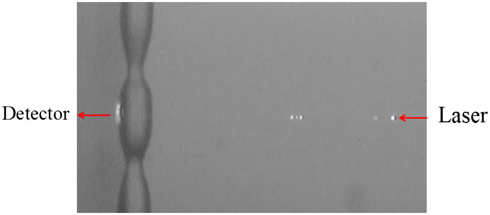
Figure 1.Micrograph of the SLM immersed in water. The fiber taper is placed under the SLM and some scattering points on it are clearly shown.
We experimentally observed the dependence of the transmission spectrum on the position of the SLM by moving the SLM to the left along the fiber taper (see Fig. 1). It was found that the line shape of the transmission spectrum changed periodically as we moved the SLM, with a period about of 9 μm. Figure 2 shows five typical transmission spectra with different positions of the SLM in one period. From Figs. 2(a) to 2(e), the SLM was moved to the left and the value of in the subfigures describes the relative positions of the SLM along the fiber taper. The line shapes of three modes are observed, and from left to right they are marked as mode 1, mode 2, and mode 3 as shown in Fig. 2(a). It can be observed that mode 3 has a symmetric line shape irrelevant to the position of the SLM. However, the line shapes of mode 1 and mode 2 show strong dependence on the position of the SLM, and they have different dependence patterns. For mode 1, as the SLM is moved to the left, the line shape evolves from an approximate symmetric dip in Fig. 2(a) to an asymmetric Fano-like resonance line shape with a higher shoulder on the right in Fig. 2(b), to a symmetric peak in Fig. 2(c), to an asymmetric Fano-like resonance line shape with a higher shoulder on the left in Fig. 2(d), and finally back to an approximate symmetric dip in Fig. 2(e). For mode 2, however, no symmetric peak is observed and its evolution is different from mode 1 as shown in Fig. 2.

Figure 2.Experimental transmission spectra with different positions of the SLM. From top to bottom, the SLM was moved to the left along the fiber taper.
3. THEORETICAL MODEL
A theory is needed to explain the observed interesting dependence of the transmission spectrum on the position of the SLM. We model the fiber taper as a waveguide with an embedded partially reflecting element as shown in Fig. 3. The experimental basis is that there are some scattering points in the fiber taper as shown in Fig. 1, which are made due to the non-uniform heating and pulling during its fabrication. These scattering points can reflect light back to the microresonator. It can be seen that the embedded partially reflecting element brings a feedback to the input. In the theoretical model, clockwise (CW) and counterclockwise (CCW) modes of the microresonator are considered. The light fields in the CW and CCW modes are denoted by and , respectively. The dynamic equations for the fields are [15] where , , and (, , ) are the resonance angular frequency, intrinsic loss rate, and loss rate to the fiber taper of the CW (CCW) mode, respectively; is the mode-coupling strength; and is the total input in the waveguide including the feedback. There is where is the original input in the waveguide when the microresonator is far away from the fiber taper, is the amplitude reflection coefficient of the partially reflecting element, and is a phase between the original input and the feedback. It is obvious from Fig. 3 that the value of will increase when the microresonator is moved to the left. The output is The transmission normalized to the original input is which is the theoretical quantity related to the experiment.
Figure 3.Microresonator side-coupled to a waveguide. The waveguide together with the embedded partially reflecting element simulates the function of the fiber taper in the experiment.
Assume that with a constant and the system is in the stationary condition. Then there is with where and . The quantity describes how the original input is modified by the feedback to get a total input . The output can be written as with which is independent of the feedback and describes the transmission of the total input to the output . Since there is , the transmission normalized to the original input can be rewritten as It can be proved that there is , but in some cases with special parameters there are . This is the reason why there are peaks in our observed spectra. We note that does not mean the input light can be amplified after the transmission of the system, which is only a case of normalization.
The fact that the line shape of mode 3 does not depend on the position of the SLM can be simply explained by assuming in the theoretical model, i.e., for mode 3 there is no coupling between the CW and CCW modes and the CCW mode cannot be excited. The situation is similar to the case where there is not the partially reflecting element in the fiber taper. For mode 3, the effect of the partially reflecting element is only to reduce the laser input.
To explain the dependence of the line shapes of mode 1 and mode 2 on the position of the SLM, assume that the resonance angular frequencies of the CW and CCW modes have the same value, i.e., . We now replace and in the theoretical transmission in Eq. (8) by . The transmission as a function of and can be plotted by giving the values of the parameters , , , , , and , and two such plots are given in Figs. 4 and 5. Figure 4 simulates the dependence of the line shape of mode 1 on the position of the SLM. It can be seen in Fig. 4 that, as the increases from to , the line shape of evolves from an approximate symmetric dip to an asymmetric Fano-like resonance line shape with a higher shoulder on the right, to a symmetric peak, to an asymmetric Fano-like resonance line shape with a higher shoulder on the left, and finally back to an approximate symmetric dip. The evolution of the simulated line shape in Fig. 4 captures the major characteristics of the observed evolution of the line shape of mode 1 in the experiment, as we moved the SLM to the left. In Fig. 6, we compare the experimental line shapes of mode 1 with the simulated line shapes, where a correspondence between the position of the SLM and the value of is given. It can be seen that qualitatively the experimental line shapes and the simulated line shapes are similar. Figure 5 simulates the dependence of the line shape of mode 2 on the position of the SLM, and in Fig. 7 we compare the experimental line shapes of mode 2 with the simulated line shapes. It can be seen in Fig. 7 that the simulated line shapes capture the major features of the experimental line shapes of mode 2. Therefore, the theoretical model is acceptable to explain the dependence of the line shapes of the three modes on the position of the SLM.
Figure 4.Simulation of the dependence of the line shape of mode 1 on the position of the SLM. Increasing the value of means moving the SLM to the left. The simulation parameters are , , , , , , and .
Figure 5.Simulation of the dependence of the line shape of mode 2 on the position of the SLM. Increasing the value of means moving the SLM to the left. The simulation parameters are , , , , , , and .
Figure 6.Comparison between the experimental line shapes and simulated line shapes for mode 1. Experimental line shapes are normalized and shifted for clarity. Simulated line shapes are also shifted and they are plotted using the same parameters as those in Fig. 4.
Figure 7.Comparison between the experimental and simulated line shapes for mode 2. Experimental line shapes are normalized and shifted for clarity. Simulated line shapes are also shifted and they are plotted using the same parameters as those in Fig. 5.
4. DISCUSSION AND SUMMARY
It was observed that the transmission spectrum changed periodically as the SLM was moved to the left, and the period was about 9 μm. In the theoretical model, if the waveguide is assumed to be a single-mode waveguide and the effective refractive index for the guiding mode is , the moved distance of the microresonator and the increase of has the relation , with being the wavelength of the laser. For one period , and therefore the calculated period will be , but it cannot be comparable with the observation. The reason can be that the fiber taper is not a single-mode waveguide. When it is a multi-mode waveguide, the previous result shows that the calculated period will be [18], where is the difference of the effective refractive index of two guiding modes. The observed period 9 μm means , which is possible for the fiber taper immersed in deionized water.
In summary, we observe the dependence of the transmission spectra of an SLM on the coupling position between the SLM and the fiber taper in aqueous environment. When the SLM is moved along the fiber taper, three modes show different evolution patterns. Line shapes like asymmetric Fano-like resonance line shapes, symmetric peaks, and dips are observed with different positions of the SLM. The fiber taper is regarded as a waveguide with an embedded partially reflecting element to explain the observation. The observation of Fano-like resonance in aqueous environment has potential biosensor applications.
References
[1] U. Fano. Effects of configuration interaction on intensities and phase shifts. Phys. Rev., 124, 1866-1878(1961).
[2] A. E. Miroshnichenko, S. Flach, Y. S. Kivshar. Fano resonances in nanoscale structures. Rev. Mod. Phys., 82, 2257-2298(2010).
[3] S. Fan. Sharp asymmetric line shapes in side-coupled waveguide-cavity systems. Appl. Phys. Lett., 80, 908-910(2002).
[4] C.-Y. Chao, L. J. Guo. Biochemical sensors based on polymer microrings with sharp asymmetrical resonance. Appl. Phys. Lett., 83, 1527-1529(2003).
[5] F. Wan, G. Qian, R. Li, J. Tang, T. Zhang. High sensitivity optical waveguide accelerometer based on Fano resonance. Appl. Opt., 55, 6644-6648(2016).
[6] K. Totsuka, N. Kobayashi, M. Tomita. Slow light in coupled-resonator-induced transparency. Phys. Rev. Lett., 98, 213904(2007).
[7] G. C. Righini, Y. Dumeige, P. Féron, M. Ferrari, G. N. Conti, D. Ristic, S. Soria. Whispering gallery mode microresonators: fundamentals and applications. Riv. Nuovo Cimento Soc. Ital. Fis., 34, 435-488(2011).
[8] Y.-F. Xiao, Q. Gong. Optical microcavity: from fundamental physics to functional photonics devices. Sci. Bull., 61, 185-186(2016).
[9] F. Bo, X. Wang, Y. Li, F. Gao, G. Zhang, J. Xu. Mode characteristics of silver-coated inverted-wedge silica microdisks. Sci. Chin. Phys. Mech. Astron., 58, 114207(2015).
[10] J. Lin, Y. Xu, Z. Fang, M. Wang, N. Wang, L. Qiao, W. Fang, Y. Cheng. Second harmonic generation in a high-Q lithium niobate microresonator fabricated by femtosecond laser micromachining. Sci. Chin. Phys. Mech. Astron., 58, 114209(2015).
[11] Z. Shen, Z.-H. Zhou, C.-L. Zou, F.-W. Sun, G.-P. Guo, C.-H. Dong, G.-C. Guo. Observation of high-Q optomechanical modes in the mounted silica microspheres. Photon. Res., 3, 243-247(2015).
[12] S. Zhu, Y. Liu, L. Shi, X. Xu, X. Zhang. Extinction ratio and resonant wavelength tuning using three dimensions of silica microresonators. Photon. Res., 4, 191-196(2016).
[13] L.-X. Zou, Y.-Z. Huang, X.-M. Lv, B.-W. Liu, H. Long, Y.-D. Yang, J.-L. Xiao, Y. Du. Modulation characteristics and microwave generation for AlGaInAs/InP microring lasers under four-wave mixing. Photon. Res., 2, 177-181(2014).
[14] W. Liang, L. Yang, J. K. S. Poon, Y. Huang, K. J. Vahala, A. Yariv. Transmission characteristics of a Fabry–Perot etalon-microtoroid resonator coupled system. Opt. Lett., 31, 510-512(2006).
[15] B. Peng, Ş. K. Özdemir, W. Chen, F. Nori, L. Yang. What is and what is not electromagnetically induced transparency in whispering-gallery microcavities. Nat. Commun., 5, 5082(2014).
[16] C. Zheng, X. Jiang, S. Hua, L. Chang, G. Li, H. Fan, M. Xiao. Controllable optical analog to electromagnetically induced transparency in coupled high-Q microtoroid cavities. Opt. Express, 20, 18319-18325(2012).
[17] Y.-F. Xiao, M. Li, Y. C. Liu, Y. Li, X. Sun, Q. Gong. Asymmetric Fano resonance analysis in indirectly coupled microresonators. Phys. Rev. A, 82, 065804(2010).
[18] B.-B. Li, Y.-F. Xiao, C.-L. Zou, X.-F. Jiang, Y.-C. Liu, F.-W. Sun, Y. Li, Q. Gong. Experimental controlling of Fano resonance in indirectly coupled whispering-gallery microresonators. Appl. Phys. Lett., 100, 021108(2012).
[19] Q. Li, T. Wang, Y. Su, M. Yan, M. Qiu. Coupled mode theory analysis of mode-splitting in coupled cavity system. Opt. Express, 18, 8367-8382(2010).
[20] A. Chiba, H. Fujiwara, J. Hotta, S. Takeuchi, K. Sasaki. Fano resonance in a multimode tapered fiber coupled with a microspherical cavity. Appl. Phys. Lett., 86, 261106(2005).
[21] Y.-F. Xiao, L. He, J. Zhu, L. Yang. Electromagnetically induced transparency-like effect in a single polydimethylsiloxane-coated silica microtoroid. Appl. Phys. Lett., 94, 231115(2009).
[22] C.-H. Dong, C.-L. Zou, Y.-F. Xiao, J.-M. Cui, Z.-F. Han, G.-C. Guo. Modified transmission spectrum induced by two-mode interference in a single silica microsphere. J. Phys. B, 42, 215401(2009).
[23] B.-B. Li, Y.-F. Xiao, C.-L. Zou, Y.-C. Liu, X.-F. Jiang, Y.-L. Chen, Y. Li, Q. Gong. Experimental observation of Fano resonance in a single whispering-gallery microresonator. Appl. Phys. Lett., 98, 021116(2011).
[24] C.-H. Dong, Z. Shen, C.-L. Zou, Y.-L. Zhang, W. Fu, G.-C. Guo. Brillouin-scattering-induced transparency and non-reciprocal light storage. Nat. Commun., 6, 6193(2015).
[25] Y. Yang, S. Saurabh, J. Ward, S. N. Chormaic. Coupled-mode-induced transparency in aerostatically tuned microbubble whispering-gallery resonators. Opt. Lett., 40, 1834-1837(2015).
[26] Y. Wang, K. Zhang, S. Zhou, Y.-H. Wu, M.-B. Chi, P. Hao. Coupled-mode induced transparency in a bottle whispering-gallery-mode resonator. Opt. Lett., 41, 1825-1828(2016).
[27] Y. Zhou, D. Zhu, X. Yu, W. Ding, F. Luan. Fano resonances in metallic grating coupled whispering gallery mode resonator. Appl. Phys. Lett., 103, 151108(2013).
[28] C. Zhao, X. Gan, L. Fang, L. Han, K. Chang, D. Li, J. Zhao. Tunable Fano-like resonance enabled by coupling a microsphere with a fiber Mach–Zehnder interferometer. Appl. Opt., 55, 5756-5760(2016).
[29] Y. Lu, L. Xu, Y. Yu, P. Wang, J. Yao. Double-wavelength Fano resonance and enhanced coupled-resonator-induced transparency in a double-microcavity resonator system. J. Opt. Soc. Am. A, 23, 1718-1721(2006).
[30] F. Lei, B. Peng, Ş. K. Özdemir, G. L. Long, L. Yang. Dynamic Fano-like resonances in erbium-doped whispering-gallery-mode microresonators. Appl. Phys. Lett., 105, 101112(2014).
[31] X.-F. Liu, F. Lei, M. Gao, X. Yang, C. Wang, Ş. K. Özdemir, L. Yang, G.-L. Long. Gain competition induced mode evolution and resonance control in erbium-doped whispering-gallery microresonators. Opt. Express, 24, 9550-9560(2016).
[32] J. Li, R. Yu, C. Ding, Y. Wu. PT-symmetry-induced evolution of sharp asymmetric line shapes and high-sensitivity refractive index sensors in a three-cavity array. Phys. Rev. A, 93, 023814(2016).
[33] F. Nazari, N. Bender, H. Ramezani, M. K. Moravvej-Farshi, D. N. Christodoulides, T. Kottos. Optical isolation via PT-symmetric nonlinear Fano resonances. Opt. Express, 22, 9574-9584(2014).
[34] Z. Shen, C.-H. Dong, Y. Chen, Y.-F. Xiao, F.-W. Sun, G. C. Guo. Compensation of the Kerr effect for transient optomechanically induced transparency in a silica microsphere. Opt. Lett., 41, 1249-1252(2016).
[35] J. Liao, X. Wu, L. Liu, L. Xu. Fano resonance and improved sensing performance in a spectral-simplified optofluidic micro-bubble resonator by introducing selective modal losses. Opt. Express, 24, 8574-8580(2016).
[36] Y.-F. Xiao, X.-F. Jiang, Q.-F. Yang, L. Wang, K. Shi, Y. Li, Q. Gong. Tunneling-induced transparency in a chaotic microcavity. Laser Photon. Rev., 7, L51-L54(2013).
[37] Y. Miao, Y. Peng, Y. Xiang, M. Li, Y. Lu, Y. Song. Dynamic Fano resonance in thin fiber taper coupled cylindrical microcavity. IEEE Photon. J., 8, 1-6(2016).
[38] X. Zhang, Y. Yang, H. Shao, H. Bai, F. Pang, H. Xiao, T. Wang. Fano resonances in cone-shaped inwall capillary based microsphere resonator. Opt. Express, 25, 615-621(2017).
[39] M.-Y. Ye, M.-X. Shen, X.-M. Lin. Transmission spectra of sausage-like microresonators. Opt. Express, 23, 25846-25853(2015).
[40] J. C. Knight, G. Cheung, F. Jacques, T. A. Birks. Phase-matched excitation of whispering-gallery-mode resonances by a fiber taper. Opt. Lett., 22, 1129-1131(1997).
[41] X.-F. Liu, F. Lei, M. Gao, X. Yang, G.-Q. Qin, G.-L. Long. Fabrication of a microtoroidal resonator with picometer precise resonant wavelength. Opt. Lett., 41, 3603-3606(2016).


