A zonal decoupling algorithm used to control a dual deformable mirror (DM) is proposed. One of the two DMs is characterized with a large stroke (woofer), while the other one is characterized by a high spatial frequency (tweeter). A numerical model is used to compare the zonal decoupling algorithm with some traditional zonal decoupling algorithms. The simulation results indicate that the algorithm presented in this Letter improves the performance in suppressing the coupling error. An experimental system is built to prove the effectiveness of this algorithm. The experiments demonstrate that the phase aberrations could be effectively compensated and that the coupling error could also be suppressed.
The laser beam clean-up systems, telescopes, and vision instruments of the next generation will require adaptive optics (AO) systems with a large stroke and high-spatial frequency[1–3]. However, it is difficult for a single deformable mirror (DM) to fulfill these requirements. To be able to compensate for phase distortion with a large amplitude and high spatial resolution, the dual DM system is proposed and widely used in different areas[1,4–8]. In the dual DM system, two DMs are used to correct the aberration cooperatively: the woofer is a DM that is characterized by a large stroke and low spatial frequency, and the tweeter is a DM that is characterized by a low stroke and high spatial frequency. A typical dual DM system used a single wavefront sensor (WFS) to measure the phase aberration, and the WFS is conjugated to the woofer and tweeter. However, a critical potential problem is that the WFS in this system only measures the residual wavefront aberration corrected by both the woofer and tweeter. If the woofer and tweeter generate the same but opposite phase compensation, which is often called coupling, the WFS could not measure the coupling, and it may induce a serious waste of the DMs’ correction ability[9]. So it is important to find a suitable algorithm to make the dual DM system work with few coupling errors. During the last decades, several control algorithms for this system have been developed, such as a two-step control algorithm[10–13], Zernike mode decomposition algorithms[1,6,7,14,15], Fourier mode decomposition algorithm[4], wavelet mode decomposition algorithm[16], distributed mode decomposition[2], and Lagrange-multiplier damped least-squares algorithms[17]. All of these algorithms could be used for special dual DM systems and have proven to be effective. For example, the Zernike mode decomposition algorithm is used for laser beam cleanup[1], the distributed mode, Fourier, or wavelet reconstruction methods are developed for large telescopes[2,4,16], and the zonal decoupling methods (two-step algorithm could be viewed as a special zonal decoupling algorithm) are often used for retina imaging[10–13,18–20]. Above all, the zonal decoupling control algorithms have the following advantages: (a) they do not need prior information on aberrations for special modes, (b) they use the correction ability of the woofer sufficiently.
We propose a novel zonal decoupling algorithm focusing on suppressing the coupling errors. The woofer is controlled by the traditional direct slope-based correction method. The control vector of the tweeter is generated by the response of the residual wavefront, and then is reset by a constraint matrix to avoid the possible coupling with the woofer. The proposed algorithm is compared with traditional zonal decoupling algorithms via simulations, and the results show that it has a better performance. Then an experimental system is set up to prove the effectiveness of our algorithm.
The direct slope method is a fast, straightforward, and flexible technique that makes the outputs of wavefront slope zero as the control target. When the slopes approach zero, it means the wavefront after-corrected limits to the reference wavefront, which is usually a flat wavefront[21].
Sign up for Chinese Optics Letters TOC. Get the latest issue of Chinese Optics Letters delivered right to you!Sign up now
We assume the is the woofer’s response matrix, and is its pseudo-inverse. So the control vector of the woofer for correcting the residual wavefront slope is: The total control vector of the woofer could be generated by the well-known digital proportional integral (PI) controller[22,23] as: where pid_a and pid_b are the coefficients that are manually tuned for specific AO systems.
The tweeter is controlled using the following steps: to make the control vector of the tweeter contain fewer couplings with the woofer, the tweeter is used only to correct the wavefront aberration, which is not corrected by the woofer. Because in most AO systems, the row number of is twice the sub-aperture number, and the column number of the equals the actuator number of the woofer, the number of rows of is often more than the number of columns[2]. We can get the slope corrected by the woofer as follows: If the control vector of the tweeter is only generated by the response of the residual slope , the coupling between the woofer and tweeter would be suppressed. As a result, the could be written as: where is an identity matrix and is the tweeter’s response matrix. If the total control vector of the tweeter could also be generated by a traditional PI controller, it could be written as: where is a constraint matrix to suppress the coupling between the woofer and tweeter. If each actuator’s influence function of the woofer could be viewed as a special mode, we could get the smallest coupling when where is the matrix containing the coefficients resulting from the projection of the tweeter’s influence functions onto the woofer’s influence functions. The value of could be calculated by two methods. One can be written as[15]: where is the th woofer’s influence function, and is the th tweeter’s influence function. All of the DMs’ influence functions can be measured by an interferometer or a WFS. The other method is written as follows[3]: Then the constraint matrix can be obtained as follow: where is an identity matrix, is a subset of the with its first rows and first columns, is the actuator number of the tweeter, and is an empirical parameter that could be calculated by simulations to make the coupling coefficient small.
Given the above, the control vectors of the woofer and tweeter could be calculated by Eqs. (2) and (5), and high correction qualities and small coupling could be both obtained when the decoupling algorithm is used.
A dual DM system is simulated to compare the algorithm proposed in this paper with several traditional zonal decoupling algorithms. A DM with 19 actuators is used as the woofer and a DM with 208 actuators is used as the tweeter in the simulations. The influence function of the two DMs is described as a Gaussian function: where is the coupling coefficient of the DM, is the position of the th actuator, is the distance between the neighboring actuators, and is the Gaussian coefficient. In the numerical model, the is set to 0.1 and is set to 2.35. In the simulations and the following experiments, the matrix in Eq. (9) is calculated as Eq. (7).
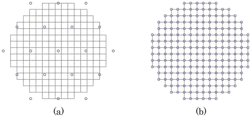
A Hartmann–Shack WFS with a lenslet array is used to measure the aberration. It is conjugated to the woofer and tweeter, and the configurations of the WFS’ sub-apertures and the DMs’ actuators are shown in Figs. 1(a) and 1(b). The initial aberration of the wavefront is made up of the first 35 Zernike polynomials, and the tip/tilt are removed completely in the numerical model because they are usually compensated by the tip-tilt mirror with another closed-loop system. The two DMs could use Eq. (5) to suppress the tip/tilt when the tip-tilt mirror is viewed as a special woofer for both the DMs.
Figure 1.Configurations of the WFS’ sub-apertures and the DM’s actuators: (a) woofer and (b) tweeter.
The coupling coefficient is used to evaluate the coupling between the correction of the woofer and tweeter, as follows: where is the correction of the woofer and is the correction of the tweeter. The smaller indicates the smaller coupling between the compensation of the woofer and tweeter[15].
A comparison between the algorithm proposed in this paper and the traditional zonal decoupling algorithms is made with the same initial aberration. A PI controller is used during these simulations, and the control parameters obtained using Eqs. (2) and (5) are 0.998 and 0.1. The control parameters could be optimized by the Ziegler–Nichols method[23]. The aberration is corrected by one of three methods: (a) the algorithm proposed in this Letter, (b) a two-step algorithm (when a two-step algorithm be used, the woofer works for the first 100 steps and the tweeter works for the second 100 steps, (c) the Lagrange-multiplier damped least-squares algorithm[14]. In this method, the Lagrange multiplier is set to the median value of the eigenvalues of the matrix , and is set to the median value of the eigenvalues of the matrix [16].
Figure 2(a) shows the root mean square (RMS) of the residual wavefront error reduction curves during correction, and Fig. 2(b) shows the coupling coefficient during the simulations. After correction by algorithm (a), the RMS is decreased to , and the coupling coefficient is kept stable at 0.003. After correction by algorithm (b), the RMS is decreased to , and the coupling coefficient is about 0.228. After correction by algorithm (c), the RMS is decreased to , and the coupling coefficient is about 0.034. This means that all these algorithms have almost the same correction performance and the algorithm proposed in this Letter would be slightly better than the others, but the algorithm could have an even better performance by suppressing the coupling between the woofer and tweeter. The simulation results indicate that the proposed algorithm has the best performance both in correction quality and suppressing coupling with the traditional zonal decoupling algorithms.
Figure 2.(a) RMS of the residual wavefront during correction. (b) Coupling coefficient during correction.
The experimental dual DM system shown in Fig. 3 is set up to evaluate the effectiveness of the algorithm proposed in this paper. Two bimorph DMs are used as the woofer and tweeter. The woofer is a bimorph DM with 19 actuators, and the tweeter is a bimorph DM with 37 actuators. Figures 4(a) and 4(b) show the actuator geometry and the clear aperture of these DMs. Besides, the experimental system is only used to prove the effectiveness of the algorithm. DMs with more actuators are often used in practical dual DM systems. However, the algorithm does not set any fundamental limitations on actuator numbers, so a dual DM system with more actuators could easily be used.
Figure 3.Schematic diagram of the experimental system.
Two experiments with different initial aberrations are carried out. For the first experiment, the initial aberration is shown in Fig. 5(a). Before correction, the RMS of the aberration is . The system parameters are the same as those used in the simulations. After being corrected only by the woofer, the RMS of the residual wavefront is decreased to , as shown in Fig. 5(b). After being corrected by a dual DM controlled by the proposed algorithm, the RMS of the residual wavefront is decreased to , as shown in Fig. 5(c). Figure 6 shows the RMS of the residual wavefront error reduction curves during the correction, which indicates that the dual DM system could improve the correction performance compared with the results when just a woofer is used.
Figure 5.(a) The initial aberration (). (b) The residual wavefront after correction only by the woofer (). (c) The residual wavefront after correction by the dual DM ().
For the second experiment, the initial aberration is shown in Fig. 7(a). Before correction, the RMS of the aberration is . The system parameters are the same as those used in the first experiment. After being corrected only by the woofer, the RMS of the residual wavefront is decreased to , as shown in Fig. 7(b). Then the tweeter joins in the correction. After being corrected by the dual DM, the RMS of the residual wavefront is decreased to , as shown in Fig. 7(c). Figure 8 shows the RMS of the residual wavefront error reduction curves during the correction, which shows that the experiment has results similar to those of the first experiment.
Figure 7.(a) The initial aberration (). (b) The residual wavefront after correction only by the woofer (). (c) The residual wavefront after correction by the dual DM ().
In the woofer-tweeter system, the coupling error accumulation is an important problem. If it is not solved, the woofer and tweeter would be start to oppose each other and become saturated over time[16]. To evaluate the effectiveness of suppressing the coupling accumulation of this algorithm, in the above experiments, the woofer-tweeter system ran more than 4000 s, and the voltage data of the woofer and tweeter are recorded at about 5 samples per second to allocate less storage. Then the phase correction of the woofer and tweeter are calculated by their voltage data, and the coupling coefficient could be obtained using Eq. (11). Figure 9 shows the coupling coefficient during 20,000 samples. It is proved that the coupling coefficient is always stable and smaller than 0.01. It indicates that the algorithm could suppress the coupling accumulation efficiently.
Figure 9.Coupling coefficient during the time experiments.
In conclusion, an effective zonal decoupling algorithm used to control the woofer-tweeter system is proposed. This algorithm can be used to the woofer-tweeter system when the woofer and tweeter have different spatial resolutions, and good correction performance and few coupling accumulations can be realized. The simulation results shows that the algorithm has a better correction performance and fewer couplings than some traditional zonal decoupling algorithms. A dual DM system is set up to evaluate the effectiveness of the algorithm. The experiment results indicate that the woofer-tweeter controlled by this algorithm has a better performance than when only a woofer is used. The effectiveness of suppressing coupling is also proved by the time experiments data. This algorithm can be used in the woofer-tweeter system for laser beam cleanup, retina imaging[24,25], and other applications for the correction of large-scale and high-spatial-resolution aberrations.