
Ruitao Yang, Hao Sun, Pengcheng Hu, Hongxing Yang, Haijin Fu, Liang Yu, Xu Xing, Xuemei Ding, Jiubin Tan, "Real-time suppression of random phase drift for laser ranging with high-frequency intermode beats," Chin. Opt. Lett. 21, 041202 (2023)
- Chinese Optics Letters
- Vol. 21, Issue 4, 041202 (2023)
Abstract
1. Introduction
Optical frequency combs provide bidirectional time traceability chains between the optical and electrical domains[1]. The time base from microwaves to optical waves is transmitted via the comb phase locking of both repetition rate (REP) and carrier-envelope phase (CEP)[2,3]. In reverse, the optical time base is transmitted back to the electrical domain via various comb-based measurement methods[4–6]. As the first absolute distance measurement method based on optical frequency comb, ranging with comb intermode beats (IMBs) has the unique advantages in terms of direct traceability and a simple principle[7–11]. With the phases of IMBs, the distance information is related to the REP and its higher-order harmonics of the frequency comb only. Since the REP can be detected and stabilized referencing to the time standard directly, ranging with the comb IMBs has attracted wide attention, particularly in space missions[8].
For this ranging method, high resolution requires a high-frequency IMB. However, the phase measurement of high-frequency IMBs is subject to the random phase drift (RPD) induced in signal transmission. The RPD is accumulated and aggravated in long-term continuous ranging. The RPD can be monitored by alternately detecting the measurement signal and a phase-constant compensating signal[9,10]. Thus, the RPD can be compensated at the cost of the measurement speed. Another solution uses frequency-modulated IMBs[11] to filter the drift by decomposing and reconstructing the phase signal via offline processing of measurement data. Its principle hinders the applications of real-time measurement.
In this Letter, we suppress the RPD of the comb IMBs in real time using two IMBs with similar frequencies from different combs. In Section 2, we theoretically analyze RPD sources in conventional methods and then propose a real-time suppression method. The proposed method requires one signal comb to probe the target and another local comb to monitor the RPD in real time. The phase difference measurement of the two IMBs is equivalent to the phase measurement of the probing signal comb IMBs, yet with the RPD deeply suppressed. In Section 3, a real-time suppression experiment is demonstrated using the two IMBs at 1001 and 1000 MHz. To characterize the RPD and isolate the phase jitter effect, data are analyzed with Allan deviation at a relatively longer sampling time. After the suppression, the RPD is merely 1 µm at a 100 s sampling time, with a 19-fold suppression realized.
Sign up for Chinese Optics Letters TOC. Get the latest issue of Chinese Optics Letters delivered right to you!Sign up now
2. Analysis and Method
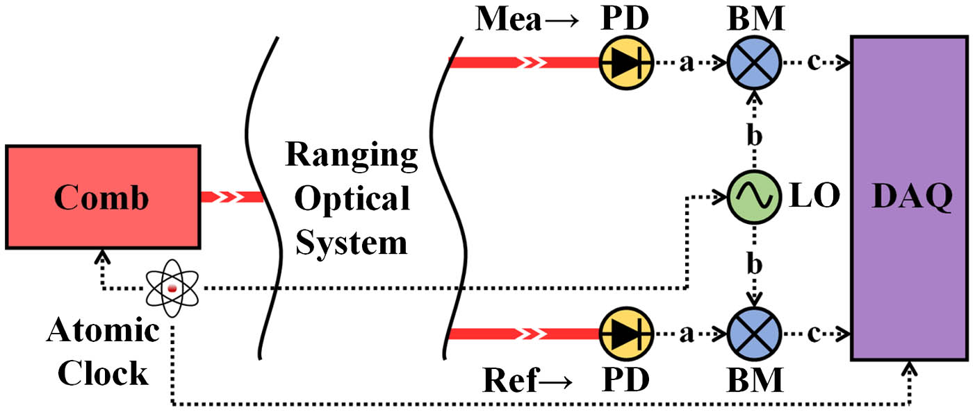
To analyze the RPD sources, Fig. 1 shows a typical example of the signal processing in ranging with the comb IMBs. The frequency comb is separated into the measurement and reference paths, respectively. The IMBs from both paths are detected to extract the distance-related relative phase shift
![]()
Figure 1.Typical example of downconversion signal processing in ranging with comb IMBs. Mea, measurement signal; Ref, reference signal; PD, photodetector; BM, balanced mixer; LO, local oscillator; DAQ, data acquisition.
To reveal the source of RPD, the signal transmission path of IMBs should be analyzed. In the measurement of phase shift
Equation (3) explains the sources of the RPD
Based on the aforementioned error source analysis, a system diagram of the real-time RPD suppression is proposed in Fig. 2. The signal comb generates the IMB with the frequency of
![]()
Figure 2.System diagram of the real-time RPD suppression. BS, beam splitter.
The random time delays
When the phase
There is a total of three items in Eq. (7). The first item is the phase
Compared with Eq. (3), the RPD
3. Experiments
Figure 3 demonstrates the experimental setup of ranging with the comb IMBs suppressing the RPD in real time. The signal comb is based on a self-made mode-locked laser with an REP of 43.52 MHz, whereas the local comb is a commercial one with a 250 MHz REP. Four polarization beam splitters (PBSs) determine the beam direction, as indicated by white arrows. With the signal comb beam (colored in red) split by PBS–1, the reflected light (namely, the reference beam) is received by the reference PD, whereas the transmitted light (namely, the measurement beam) probes the target reflector and then returns to the measurement PD. Thus, the signal comb carries distance-dependent phase information in the IMBs. Meanwhile, the local comb carries a constant phase in the beats, with the beams (colored in blue) propagating at a fixed distance. The extraction of phase information requires that the IMBs generated by the PDs be downconverted. The 23rd-order beats of the signal comb (with a frequency of
![]()
Figure 3.Experimental setup of ranging with the comb IMBs suppressing the RPD in real time. PBS, polarization beam splitter; H, half-wave plate; Q, quarter-wave plate; PS, power splitter; BPF, bandpass filter.
It should be noted that the accurate phase measurement of IMBs requires the PDs to operate in the linear region[14]. Otherwise, saturated PDs will introduce dynamic phase retardation related to the pulse energy fluctuation[15] into the initial phase shift
To identify the linear operation region, the radio-frequency (RF) response of the PDs is studied. Figure 4 depicts the response of the measurement PDs detecting the two combs separately or simultaneously. Both PDs are the identical model (Menlo Systems APD310, with a bandwidth of 1.6 GHz) and hence have nearly the same response curves. The linear region (shadowed in green) and the nonlinear region (shadowed in yellow) can be distinguished from each curve in Fig. 4. Taking Fig. 4(a) as an example, the signal comb (43.52 MHz REP) is detected individually by the measurement PD. In the linear region, the RF power of the IMB of
![]()
Figure 4.RF response of the measurement PD. (a) Beat fIMB with the signal comb detected individually; (b) beat fIMBL with the local comb detected individually; (c) beat fIMB and (d) beat fIMBL with the two combs (of the same optical power) detected simultaneously. P1 dB, RF power at the 1-dB compression point.
Figure 5 shows the experimental results of the real-time RPD suppression. The reflector target is fixed at a short distance of about 0.5 m to reduce the influence on the RPD from the air refractive index variation and the foundation thermal expansion. The distance variation is continuously measured with the IMBs for 40 min and updated every 0.5 s with the acquiring time of 20 ms. Figure 5(a) compares the results without (colored in red) and with (colored in black) the real-time suppression. During the measurement, artificial disturbances were imposed to simulate a severe environment. A section of signal-transmission cable was gripped in hand for warming up rapidly and bending to simulate violent temperature changes and thermal deformation. In this process, the measurement result drifted for up to 150 µm. Meanwhile, the effect of vibration was simulated by knocking on the cables at the 25th minute, and an instant rise of about 50 µm was observed in the curve. For the other times, the measurement result drifted relatively slowly, mainly attributed to slight room temperature fluctuations. Comparatively, the measurement results with the suppression were much stabler. The effects of gripping and knocking could not be identified from the suppressed results, indicating the proposed method works effectively on the drifts and instant changes. Figure 5(b) gives the Y-scale zoom-in details of the suppressed results in Fig. 5(a). The overall distance variation is about 55 µm. However, the method is proposed to suppress the relatively long-term RPD. Therefore, the suppressed results are smoothed by a 10 s adjacent-averaging. Accordingly, the peak-to-peak fluctuation of the corresponding green curve in Fig. 5(b) is down to 20 µm, significantly decreasing from the total drift of 220 µm for the red curve in Fig. 5(a). To show the long-term drift suppression effect quantitatively and mitigate the influence of the short-term jitters, the measurement results are analyzed with Allan deviation, as shown in Fig. 5(c)[19]. With the increasing of sampling time from 0.5 s to 100 s, the Allan deviation of the original result first decreases from 6 µm (0.5 s) to 3 µm (5 s) and then increases up to 19 µm (100 s). When the proposed method is applied, the same condition Allan deviation of the suppressed result decreases from 8 µm (0.5 s) to 1 µm (100 s) monotonically. The 100 s long-term Allan deviation has been reduced to 1/19 of the original data, further proving the effectiveness of the drift suppression.
![]()
Figure 5.Experimental results of real-time RPD suppression. (a) Comparison of the distance variation measurement results without and with the real-time suppression; (b) zoom-in details of the suppressed results in the Y-scale; (c) Allan deviation of the measurement results with and without the RPD suppression.
4. Conclusion
We propose a real-time suppression method for the RPD in ranging with high-frequency comb IMBs. The mechanism of RPD generation is analyzed and modeled from the aspect of signal transmission. Two IMBs of similar frequencies from different combs are applied to suppress the RPD. The drift suppression performance is quantitatively evaluated using Allan deviation. For the 100 s sampling time, the Allan deviation is suppressed from 19 to 1 µm with the proposed method. The proposed method provides a new solution for the long-standing phase drift problem in laser ranging with high-frequency comb IMBs. Although the PDs are easier to be saturated by the two combs, we believe combs with higher REPs will solve the problem and further improve measurement precision. For the future, we are looking forward to realizing high-REP combs with ultrashort fiber cavities.
References
[1] J. Ye, H. Schnatz, L. W. Hollberg. Optical frequency combs: from frequency metrology to optical phase control. IEEE J. Sel. Top. Quantum Electron., 9, 1041(2003).
[2] J. Kim, Y. Song. Ultralow-noise mode-locked fiber lasers and frequency combs: principles, status, and applications. Adv. Opt. Photonics, 8, 465(2016).
[3] F. W. Helbing, G. Steinmeyer, U. Keller. Carrier-envelope offset phase-locking with attosecond timing jitter. IEEE J. Sel. Top. Quantum Electron., 9, 1030(2003).
[4] R. Yang, F. Pollinger, K. Meiners-Hagen, J. Tan, H. Bosse. Heterodyne multi-wavelength absolute interferometry based on a cavity-enhanced electro-optic frequency comb pair. Opt. Lett., 39, 5834(2014).
[5] Z. Zhu, G. Wu. Dual-comb ranging. Engineering, 4, 772(2018).
[6] T. Fortier, E. Baumann. 20 years of developments in optical frequency comb technology and applications. Commun. Phys., 2, 153(2019).
[7] K. Minoshima, H. Matsumoto. High-accuracy measurement of 240-m distance in an optical tunnel by use of a compact femtosecond laser. Appl. Opt., 39, 5512(2000).
[8] Y.-S. Jang, W. Kim, H. Jang, S.-W. Kim. Absolute distance meter operating on a free-running mode-locked laser for space mission. Int. J. Precis. Eng. Manuf., 19, 975(2018).
[9] D. Salido-Monzú, A. Wieser. Simultaneous distance measurement at multiple wavelengths using the intermode beats from a femtosecond laser coherent supercontinuum. Opt. Eng., 57, 044107(2018).
[10] N. R. Doloca, K. Meiners-Hagen, M. Wedde, F. Pollinger, A. Abou-Zeid. Absolute distance measurement system using a femtosecond laser as a modulator. Meas. Sci. Technol., 21, 115302(2010).
[11] X. Xu, Z. Zhang, H. Zhang, H. Zhao, W. Xia, M. He, J. Li, J. Zhai, H. Wu. Long distance measurement by dynamic optical frequency comb. Opt. Express, 28, 4398(2020).
[12] R. Papazyan, R. Eriksson. Calibration for time domain propagation constant measurements on power cables. IEEE Trans. Instrum. Meas., 52, 415(2003).
[13] S. Yokoyama, A. Okamoto, T. Araki, N. Suzuki. Examination to eliminate undesirable phase delay of an avalanche photodiode (APD) for intensity-modulated light. Rev. Sci. Instrum., 66, 5331(1995).
[14] R. Bouchand, D. Nicolodi, X. Xie, C. Alexandre, Y. L. Coq. Accurate control of optoelectronic amplitude to phase noise conversion in photodetection of ultra-fast optical pulses. Opt. Express, 25, 12268(2017).
[15] M. Currie, I. Vurgaftman. Microwave phase retardation in saturated InGaAs photodetectors. IEEE Photon. Technol. Lett., 18, 1433(2006).
[16] T. Bosch, M. Lescure. Crosstalk analysis of 1 m to 10 m laser phase-shift range finder. IEEE Trans. Instrum. Meas., 46, 1224(1997).
[17] H. Fu, Y. Wang, P. Hu, J. Tan, Z. Fan. Nonlinear errors resulting from ghost reflection and its coupling with optical mixing in heterodyne laser interferometers. Sensors, 18, 758(2018).
[18] H. Jiang, J. Taylor, F. Quinlan, T. Fortier, S. A. Diddams. Noise floor reduction of an Er:fiber laser-based photonic microwave generator. IEEE Photonics J., 3, 1004(2011).
[19] D. Allan. Statistics of atomic frequency standards. Proc. IEEE, 54, 221(1966).


Set citation alerts for the article
Please enter your email address

© Copyright 2018-2021 | Chinese Laser Press. All Rights Reserved 沪ICP备15018463号-20