• Photonics Research
  • Vol. 3, Issue 6, 313 (2015)
Zhengqing Qi1, Jie Yao1、2, Liangliang Zhao1, Yiping Cui1, and Changgui Lu1、*
Author Affiliations
  • 1Advanced Photonics Center, Southeast University, Nanjing 210096, China
  • 2Nanjing Normal University, Nanjing 210023, China
  • show less
    DOI: 10.1364/PRJ.3.000313 Cite this Article Set citation alerts
    Zhengqing Qi, Jie Yao, Liangliang Zhao, Yiping Cui, Changgui Lu. Tunable double-resonance dimer structure for surface-enhanced Raman scattering substrate in near-infrared region[J]. Photonics Research, 2015, 3(6): 313 Copy Citation Text show less
    Schematic of double-resonance gold dimer array substrate.
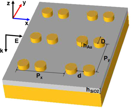
    Fig. 1. Schematic of double-resonance gold dimer array substrate.
    (a) Simulated electric field intensity enhancement factors of the dimer grating (green solid line), the single disk grating (black square line), a single dimer (red circle line), and a single disk (blue triangle line) upon gold film separated by a layer of silica spacer. (b) Ez amplitude at position 2 for the gold dimer array case. (c) Schematics of the four structures simulated.
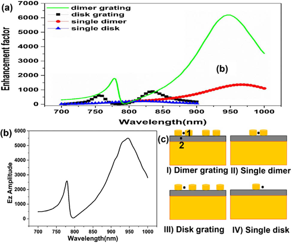
    Fig. 2. (a) Simulated electric field intensity enhancement factors of the dimer grating (green solid line), the single disk grating (black square line), a single dimer (red circle line), and a single disk (blue triangle line) upon gold film separated by a layer of silica spacer. (b) Ez amplitude at position 2 for the gold dimer array case. (c) Schematics of the four structures simulated.
    (a) Intensity (|E|2) distribution on the half-height surface of the gold disk with hSiO2=45 nm at 785 nm (SPR) with maximum intensity 2042. (b) 950 nm (LSPR) with maximum intensity 7066 corresponding to the two resonant modes of the dimer grating case in Fig. 2(a), respectively.
    Fig. 3. (a) Intensity (|E|2) distribution on the half-height surface of the gold disk with hSiO2=45nm at 785 nm (SPR) with maximum intensity 2042. (b) 950 nm (LSPR) with maximum intensity 7066 corresponding to the two resonant modes of the dimer grating case in Fig. 2(a), respectively.
    (a) Simulated electric field spectrum for the structure with Px=550 nm, Py=500 nm, and d=60 nm at different thicknesses of the silica spacer. (b) Holistic enhancement GSERS via the change of the thickness of the silica spacer.
    Fig. 4. (a) Simulated electric field spectrum for the structure with Px=550nm, Py=500nm, and d=60nm at different thicknesses of the silica spacer. (b) Holistic enhancement GSERS via the change of the thickness of the silica spacer.
    Electric field spectrum with Px=550 nm, Py=500 nm, and hSiO2=45 nm at different interparticle separations: 15 nm (black line), 30 nm (red dot-dotted dash line), and 45 nm (blue dotted–dashed line).
    Fig. 5. Electric field spectrum with Px=550nm, Py=500nm, and hSiO2=45nm at different interparticle separations: 15 nm (black line), 30 nm (red dot-dotted dash line), and 45 nm (blue dotted–dashed line).
    d (nm)VeffQQ/Veff
    151.16E48.487.33E4
    201.59E49.075.69E4
    252.05E49.684.71E4
    302.45E410.164.14E4
    352.84E410.553.71E4
    453.61E411.453.17E4
    654.78E413.342.79E4
    Single dimer with a gap of 15 nm2.71E44.041.49E4
    Single disk1.33E35.964.48E3
    Table 1. Normalized Effective Mode Volume and the Quality Factor for Different Interparticle Separation Dimers, a Single Dimer with a Gap of 15  nm, and a Single Disk upon Gold Film Separated by a Layer of Silica Spacer
    Zhengqing Qi, Jie Yao, Liangliang Zhao, Yiping Cui, Changgui Lu. Tunable double-resonance dimer structure for surface-enhanced Raman scattering substrate in near-infrared region[J]. Photonics Research, 2015, 3(6): 313
    Download Citation