• Chinese Journal of Lasers
  • Vol. 48, Issue 4, 0401009 (2021)
Zefeng Wang1、2、3、*, Zhiyue Zhou1, Yulong Cui1, Wei Huang1, Zhixian Li1, and Hao Li1
Author Affiliations
  • 1College of Advanced Interdisciplinary Studies, National University of Defense Technology, Changsha, Hunan 410073, China
  • 2State Key Laboratory of Pulsed Power Laser Technology, Changsha, Hunan 410073, China
  • 3Hunan Provincial Key Laboratory of High Energy Laser Technology, Changsha, Hunan 410073, China
  • show less
    DOI: 10.3788/CJL202148.0401009 Cite this Article Set citation alerts
    Zefeng Wang, Zhiyue Zhou, Yulong Cui, Wei Huang, Zhixian Li, Hao Li. Research Progress and Prospect of Fiber Gas Laser Sources (II): Based on Population Inversion[J]. Chinese Journal of Lasers, 2021, 48(4): 0401009 Copy Citation Text show less
    Comparison of laser wavebands generated by typical fiber gas laser and fiber laser[1]
    Fig. 1. Comparison of laser wavebands generated by typical fiber gas laser and fiber laser[1]
    Diagrams of energy level transition. (a) Diagram of energy level transition of C2H2 molecules pumped with P branch absorption lines; (b) diagram of energy level transition of CO2 molecules pumped with R branch absorption lines
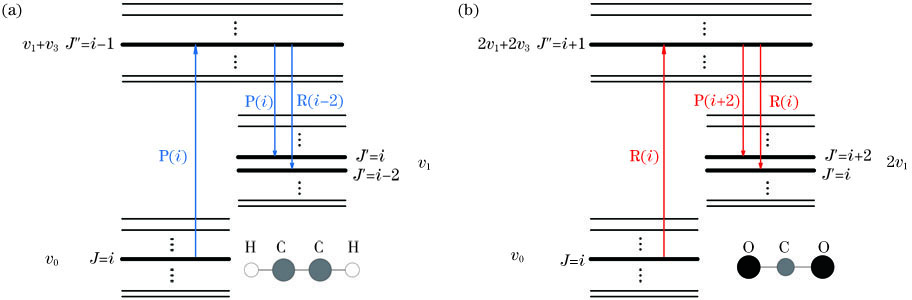
    Fig. 2. Diagrams of energy level transition. (a) Diagram of energy level transition of C2H2 molecules pumped with P branch absorption lines; (b) diagram of energy level transition of CO2 molecules pumped with R branch absorption lines
    Diagram of fiber gas laser based on population inversion
    Fig. 3. Diagram of fiber gas laser based on population inversion
    3 μm laser generation from acetylene-filled Kagome HCF pumped by OPO[2]. (a) Experimental setup; (b) output 3 μm laser spectrum
    Fig. 4. 3 μm laser generation from acetylene-filled Kagome HCF pumped by OPO[2]. (a) Experimental setup; (b) output 3 μm laser spectrum
    Single-pass configuration experiment using acetylene-filled anti-resonant HCF pumped by tunable diode laser [4]. (a) Diagram of experimental setup; (b) laser pulse energy varying with absorbed pump pulse energy at different pressure
    Fig. 5. Single-pass configuration experiment using acetylene-filled anti-resonant HCF pumped by tunable diode laser [4]. (a) Diagram of experimental setup; (b) laser pulse energy varying with absorbed pump pulse energy at different pressure
    Ring-cavity configuration experiment using acetylene-filled anti-resonant HCF pumped by diode laser[6].(a) Diagram of experimental setup; (b) output spectra for different pump wavelengths
    Fig. 6. Ring-cavity configuration experiment using acetylene-filled anti-resonant HCF pumped by diode laser[6].(a) Diagram of experimental setup; (b) output spectra for different pump wavelengths
    Single-pass configuration experiment of fiber acetylene gas CW laser output[7]. (a) Diagram of experimental setup; (b) output laser power as a function of absorbed pump power at different pressure
    Fig. 7. Single-pass configuration experiment of fiber acetylene gas CW laser output[7]. (a) Diagram of experimental setup; (b) output laser power as a function of absorbed pump power at different pressure
    Experiment for measuring output beam quality of fiber acetylene gas laser[8]. (a) Experimental setup; (b) M2 value corresponding to different output pulse energy
    Fig. 8. Experiment for measuring output beam quality of fiber acetylene gas laser[8]. (a) Experimental setup; (b) M2 value corresponding to different output pulse energy
    Experiment of OPO pumping CO2-filled silver plating capillary[1]. (a) Diagram of experimental setup; (b) output spectrum and energy level transition principle
    Fig. 9. Experiment of OPO pumping CO2-filled silver plating capillary[1]. (a) Diagram of experimental setup; (b) output spectrum and energy level transition principle
    Experimental setup and results of CO2 laser based on anti-resonant HCFs[13]. (a) Diagram of experimental setup; (b) schematic diagram of energy level transition; (c) output spectrum; (d) output power at 4 μm varying with absorbed pump power
    Fig. 10. Experimental setup and results of CO2 laser based on anti-resonant HCFs[13]. (a) Diagram of experimental setup; (b) schematic diagram of energy level transition; (c) output spectrum; (d) output power at 4 μm varying with absorbed pump power
    Experiment of thulium-doped fiber amplifier pumping HBr-filled anti-resonant HCF[14]. (a) Diagram of experimental setup; (b) output spectrum and energy level transition principle
    Fig. 11. Experiment of thulium-doped fiber amplifier pumping HBr-filled anti-resonant HCF[14]. (a) Diagram of experimental setup; (b) output spectrum and energy level transition principle
    Experimental setup and output spectrum of CW light pumped I2 vapor fiber gas laser[5]. (a) Experimental setup;(b) output laser spectrum
    Fig. 12. Experimental setup and output spectrum of CW light pumped I2 vapor fiber gas laser[5]. (a) Experimental setup;(b) output laser spectrum
    Experiments of 3 μm laser radiation from electrically excited He-Xe gas based on anti-resonant HCF[41]. (a) Diagram of experimental setup and output signals for different fiber lengths; (b) output laser spectrum
    Fig. 13. Experiments of 3 μm laser radiation from electrically excited He-Xe gas based on anti-resonant HCF[41]. (a) Diagram of experimental setup and output signals for different fiber lengths; (b) output laser spectrum
    Coupling by inserting tapered solid-core fiber into HCF[47]
    Fig. 14. Coupling by inserting tapered solid-core fiber into HCF[47]
    Coupling efficiency of tapered fiber and anti-resonant HCF varying with waist diameter[48]. (a) Coupling efficiency of tapered fiber HI-1060 and ice-cream anti-resonant HCF at 1064 nm varying with waist diameter. Inset is output near field from HCF; (b) coupling efficiency of tapered SMF-28 and node-less anti-resonant HCF at 1568 nm varying with waist diameter
    Fig. 15. Coupling efficiency of tapered fiber and anti-resonant HCF varying with waist diameter[48]. (a) Coupling efficiency of tapered fiber HI-1060 and ice-cream anti-resonant HCF at 1064 nm varying with waist diameter. Inset is output near field from HCF; (b) coupling efficiency of tapered SMF-28 and node-less anti-resonant HCF at 1568 nm varying with waist diameter
    Gas gainmediumPumping bandLasing band
    λ /μmVibrational statetransitionSpectral line intensity /(cm·molecule-1)λ /μmVibrational statetransitionSpectral line intensity /(cm·molecule-1)
    C2H21.51--1.55v0v1+v31.34×10-203.09--3.21v1+v3v1-
    CO1.56--1.65v=0→v=32.17×10-232.32--2.51v=3→v=13.17×10⁻²⁵
    CO2.29--2.52v=0→v=23.47×10-214.43--5.26v=2→v=12.70×10⁻²³
    CO21.99--2.06v0→2v1+v31.32×10-214.25--4.532v1+v3→2v17.55×10-24
    N2O1.98--2.02v0→3v1+2v25.00×10-232.65--2.713v1+2v2v15.97×10-24
    HI1.53--1.95v=0→v=33.22×10-224.45--7.49v=3→v=25.00×10⁻³⁰
    HBr1.94--2.72v=0→v=28.30×10-223.69--6.59v=2→v=15.63×10⁻²⁵
    Table 1. Common gas media and related parameters in mid-infrared fiber gas laser
    Pump sourcePumpwavelength /nmGas gainmediumLaserwavelength /μmMaximum laserenergy or powerEfficiency /%Ref. No.
    OPO1521C2H23.12, 3.166 nJ1[2]
    OPA1532.8C2H23.11, 3.17550 nJ20[3]
    OPA1541.3HCN3.09, 3.1556 nJ0.02[3]
    OPO2002.5CO24.30, 4.37100 μJ20[3]
    OPO1521C2H23.12, 3.16600 nJ27[1]
    Diode laser1530C2H23.12, 3.160.8 μJ30[4]
    Nd∶Vanadate532I21.31, 1.338 mW4[5]
    Diode laser1530C2H23.08--3.182.5 mW6.7[6]
    Diode laser1530C2H23.12, 3.161.12 W33.2[7]
    OPA1530C2H23.11, 3.171.41 μJ20[8]
    Diode laser1530--1535C2H23.09--3.210.6 μJ0.77 W (CW)1613[10]
    TDFA2000.6CO24.30, 4.3980 mW19.3[13]
    OPO1517N2O4.59, 4.66150 nJ9[12]
    ElectrodesHe∶Xe (5∶1)3.11, 3.37, 3.51[41]
    Table 2. Research progress of fiber gas lasers based on population inversion
    Zefeng Wang, Zhiyue Zhou, Yulong Cui, Wei Huang, Zhixian Li, Hao Li. Research Progress and Prospect of Fiber Gas Laser Sources (II): Based on Population Inversion[J]. Chinese Journal of Lasers, 2021, 48(4): 0401009
    Download Citation