• Photonics Research
  • Vol. 10, Issue 5, A66 (2022)
Aroutin Khachaturian*, Reza Fatemi, and Ali Hajimiri
Author Affiliations
  • California Institute of Technology, Pasadena, California 91125, USA
  • show less
    DOI: 10.1364/PRJ.437518 Cite this Article Set citation alerts
    Aroutin Khachaturian, Reza Fatemi, Ali Hajimiri. Achieving full grating-lobe-free field of view with low-complexity co-prime photonic beamforming transceivers[J]. Photonics Research, 2022, 10(5): A66 Copy Citation Text show less
    Solid-state beam steering methods. (a) 1D-grid aperture beam steering with a tunable laser source. (b) FOV of 1D apertures as a function of wavelength tuning range for prior art [6,7,15,17]. (c) 2D-grid aperture beam steering with a fixed-wavelength laser. (d) FOV of 2D-grid uniform apertures as a function of the number elements in the array for a different number of photonics routing layers. 2D-grid co-prime transceiver OPAs can operate in a radiating-element-limited FOV regime using a single frequency source.
    Fig. 1. Solid-state beam steering methods. (a) 1D-grid aperture beam steering with a tunable laser source. (b) FOV of 1D apertures as a function of wavelength tuning range for prior art [6,7,15,17]. (c) 2D-grid aperture beam steering with a fixed-wavelength laser. (d) FOV of 2D-grid uniform apertures as a function of the number elements in the array for a different number of photonics routing layers. 2D-grid co-prime transceiver OPAs can operate in a radiating-element-limited FOV regime using a single frequency source.
    Co-prime beamforming example for P=3, Q=4. (a) Cross section of the co-prime transmitter and receiver far-field radiation patterns. (b) Cross section of the transceiver co-prime beam showing no grating lobes and the equivalent half-wavelength spacing array far-field radiation pattern. (c) Co-prime transmitter and receiver array elements on larger than half-wavelength spacing grid. (d) Half-wavelength spacing array with beamwidth equivalent to the co-prime array. (e) Transceiver SLL as a function of array multiplication factor k. (f) Co-prime array beam steering for several directions and the resulting transceiver pattern for θRx=0° and θTx=0°.
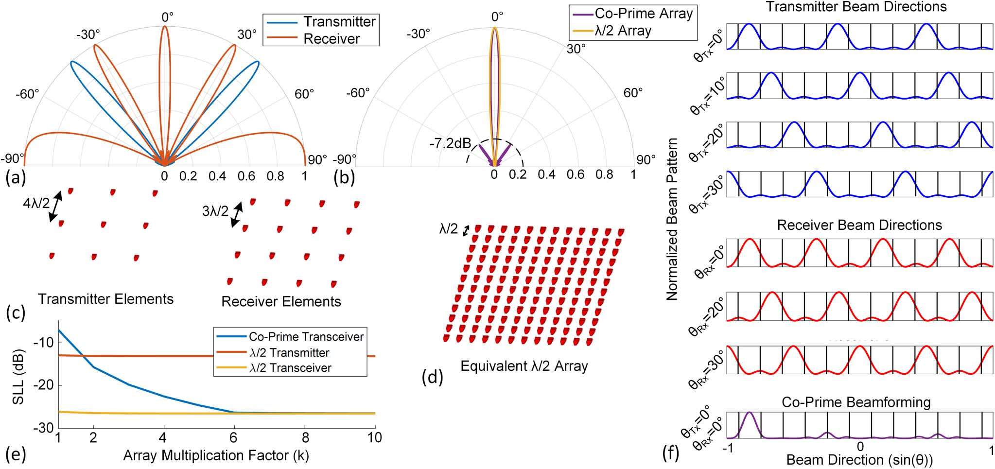
    Fig. 2. Co-prime beamforming example for P=3, Q=4. (a) Cross section of the co-prime transmitter and receiver far-field radiation patterns. (b) Cross section of the transceiver co-prime beam showing no grating lobes and the equivalent half-wavelength spacing array far-field radiation pattern. (c) Co-prime transmitter and receiver array elements on larger than half-wavelength spacing grid. (d) Half-wavelength spacing array with beamwidth equivalent to the co-prime array. (e) Transceiver SLL as a function of array multiplication factor k. (f) Co-prime array beam steering for several directions and the resulting transceiver pattern for θRx=0° and θTx=0°.
    Co-prime transceiver system architecture. (a) Block diagram of the co-prime transceiver. (b) Transmitter and receiver aperture implementations. (c) Compact radiator design. (d) Die photo of the fabricated chip. (e) Row–column drive phase modulator (PM) array. (f) Compact spiral thermal phase shifter.
    Fig. 3. Co-prime transceiver system architecture. (a) Block diagram of the co-prime transceiver. (b) Transmitter and receiver aperture implementations. (c) Compact radiator design. (d) Die photo of the fabricated chip. (e) Row–column drive phase modulator (PM) array. (f) Compact spiral thermal phase shifter.
    Co-prime transceiver measurement setup. The far-field transceiver probe always points toward the center of rotation where the transceiver chip is located. The far-field probe consists of an InGaAs photodiode for transmitter characterization and a cleaved fiber illuminating the chip with the output of SSB 1 (input laser shifted by 10 MHz) for heterodyne receiver measurements.
    Fig. 4. Co-prime transceiver measurement setup. The far-field transceiver probe always points toward the center of rotation where the transceiver chip is located. The far-field probe consists of an InGaAs photodiode for transmitter characterization and a cleaved fiber illuminating the chip with the output of SSB 1 (input laser shifted by 10 MHz) for heterodyne receiver measurements.
    Co-prime transmitter beamforming and steering using an InGaAs photodetector as the far-field probe. Grating lobes are spaced 9.55° consistent with 9.2 μm spacing of radiating elements. (a) 2D optimized beam pattern for four directions. (b) Cross section of θy plane. (c) Cross section of θx plane.
    Fig. 5. Co-prime transmitter beamforming and steering using an InGaAs photodetector as the far-field probe. Grating lobes are spaced 9.55° consistent with 9.2 μm spacing of radiating elements. (a) 2D optimized beam pattern for four directions. (b) Cross section of θy plane. (c) Cross section of θx plane.
    Co-prime receiver beamforming and steering using a cleaved fiber for illuminating the chip with the output of SSB 1 (input laser offset by 10 MHz) and output of SSB 2 (input laser offset by 11.5 MHz) as reference signal. Grating lobes are spaced 7.2° consistent with 12.4 μm spacing of radiating elements. (a) 2D optimized beam pattern for four directions. (b) Cross section of θy plane. (c) Cross section of θx plane.
    Fig. 6. Co-prime receiver beamforming and steering using a cleaved fiber for illuminating the chip with the output of SSB 1 (input laser offset by 10 MHz) and output of SSB 2 (input laser offset by 11.5 MHz) as reference signal. Grating lobes are spaced 7.2° consistent with 12.4 μm spacing of radiating elements. (a) 2D optimized beam pattern for four directions. (b) Cross section of θy plane. (c) Cross section of θx plane.
    Overlap plot of the transmitter and receiver patterns. (a) Beam patterns captured when the optimized settings are loaded separately (blue) and when both settings are loaded concurrently (orange). (b) Synthesized transceiver pattern.
    Fig. 7. Overlap plot of the transmitter and receiver patterns. (a) Beam patterns captured when the optimized settings are loaded separately (blue) and when both settings are loaded concurrently (orange). (b) Synthesized transceiver pattern.
    Aroutin Khachaturian, Reza Fatemi, Ali Hajimiri. Achieving full grating-lobe-free field of view with low-complexity co-prime photonic beamforming transceivers[J]. Photonics Research, 2022, 10(5): A66
    Download Citation