
Gaofei SUN, Shanchi MING, Guoyu ZHANG, Shi LIU, Da XU. Correction Method of Star Position Error for Splicing Star Simulator[J]. Acta Photonica Sinica, 2021, 50(9): 0912006
- Acta Photonica Sinica
- Vol. 50, Issue 9, 0912006 (2021)
Abstract
0 Introduction
From the successful docking of Shenzhou XI with Tiangong 2 to the successful launch of Long March 5, the star sensor bothplays a decisive role in its stable operation in orbit.The precision of star point position is significant to identify the star map and to acquire the aircraft attitude for star sensors [
Star point position, as the main indicator in the evaluation of the precision of star simulator, directly determines the angle precision of star simulator. In order to improve the star position accuracy, the star position should be corrected according to the design and installation results.The traditional correction method regards the different focal lengths of stars at different positions of the system as the reason for all errors. On the basis of multiple measurements, the focal length corresponding to each star point is determined, and then the new focal length is obtained based on the objective of minimizing the error, and then the corrected position of each star point under this focal length is deduced. For example, WANG Lingyun, et al corrected the star position error of Thin Film Transistor Liquid Crystal Display (TFT-LCD) star simulator, and the accuracy was better than 35"[
To this end, this study investigated the double-chip LCOS splicing star simulator and analyzed the lateral aberration theory of high precision imaging of star point position. An optical system with high imaging quality was designed. Moreover, the correction method was proposed, and a measurement model of star point position was established, expecting to provide a new idea and approach for improving the precision of star simulator.
1 Working principle
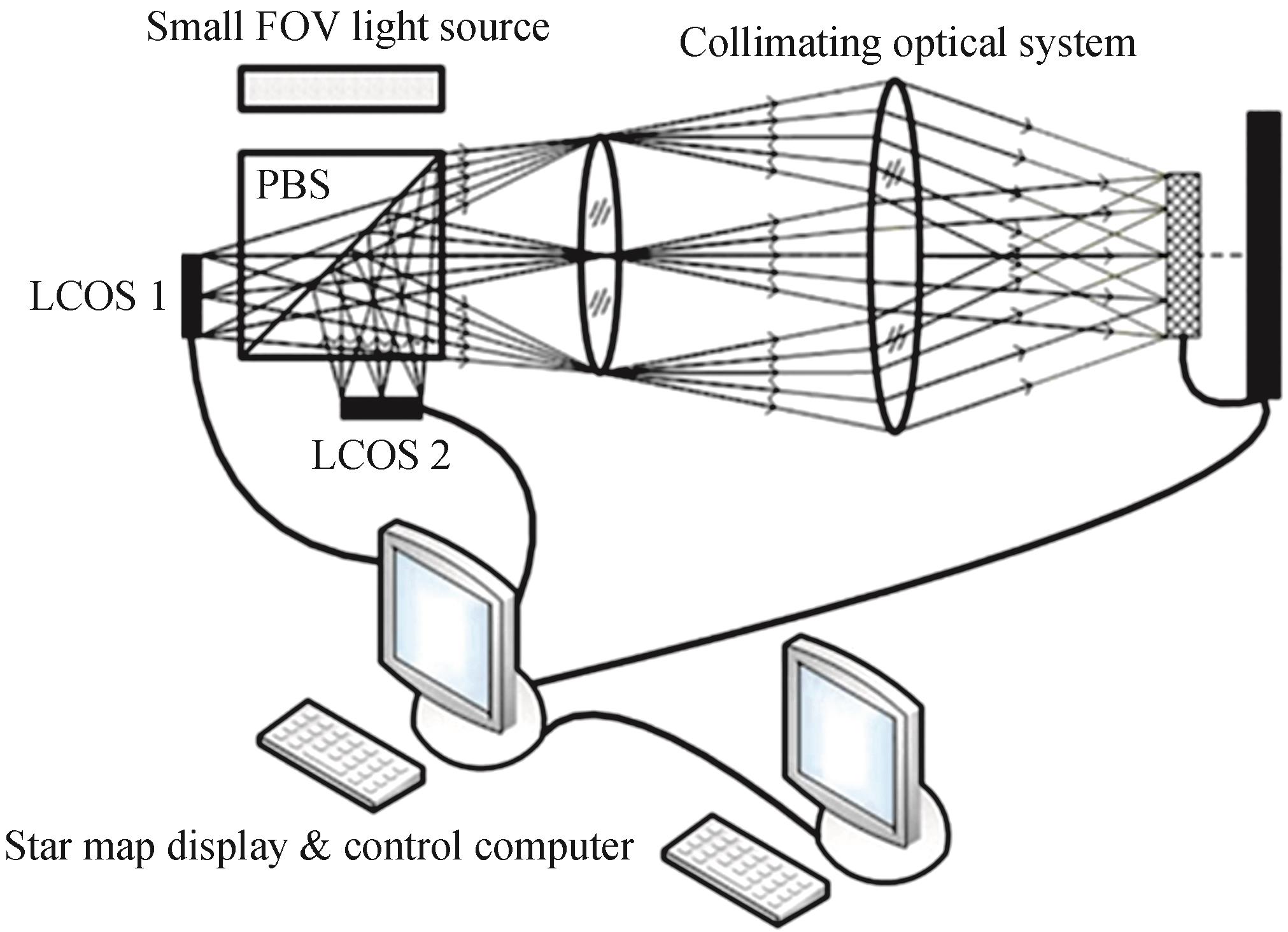
Two pieces of LCOS were spliced to realize a large field of view star simulation. The splicing star simulator consists LCOS 1, LCOS 2, Polarization Beam Splitter(PBS), small field angle light source, collimating optical system, star image display and control computer, which form a large field star map simulator. A starlight exit precision detection device composed of array CCD, its image acquisition system and high precision theodolite was used to further enhance the simulation precision of star point position. The star map information was received, and the closed loop detection and correction were implemented combined with the star map display and the control computer, as shown in Fig.1.
![]()
Figure 1.Experimental device diagram
The star map display and the control computer generate the star map data observed by the star sensor according to the orientation of the coordinate axis of the star sensor in the inertial coordinate system, and the star map is generated on LCOS 1 and LCOS 2. The LCOS 1 and LCOS 2 are combined to form a mosaic image by the action of PBS, and the stars displayed in the image become parallel light after the collimation optical system, so as to realize the simulation of star map under laboratory conditions for the observation of star sensor. The indicators of the splicing star simulator are shown in Table 1.
| Technical specifications | Index parameter |
|---|---|
| FOV | 22° |
| Caliber | 10 mm |
| Single star field angle | 35″ |
Table 1. Star simulation indicators
2 Star simulator optical system based on lateral aberration
2.1 Lateral aberration theory
The aberration of optical system is divided into monochromatic aberration and chromatic aberration. There are various aberrations in the collimating optical system of star simulator, thereby influencing the imaging position and imaging quality of star points[
![]()
Figure 2.Influence of lateral aberration on off-axis imaging beams
1) Influence of distortion on star point position
Distortion is the monochromatic aberration caused by the change of optical system magnification with the angle between the beam and the principal axis. For star simulator, the distortion of collimating optical system only influences the imaging position of star. The aberration is calculated by Eqs. (1)~(3).
where
2) Influence of coma on star point position
Coma is the asymmetry of off-axis ray of star point passing through the optical system, including the meridional coma and the sagittal coma. The meridional coma difference is three times that of the sagittal coma. The meridian coma is calculated by Eqs. (4)~(5).
where
3) Influence of field curvature on star point position
Field curvature indicates that the meridional and sagittal off-axis light beams of the star point cannot focus on a point after the action of the optical system. The meridional image points do not coincide with the sagittal image points, that is, the center and edge of the star cannot be clear simultaneously. The calculation of the field curvature is shown in Eqs. (6)~(8).
where
2.2 Evaluation of optimization parameters of collimating optical system
According to requirements for the field of view, aperture, single star angle and single star position precision of the splicing star simulator, combined with the influence of lateral aberration on imaging position and,a small distortion flat field high imaging quality collimating optical system was designed by ZEMAX. The optical structure is shown in Fig.3 and the aberration curve is shown in Fig.4.
![]()
Figure 3.Optical structure
![]()
Figure 4.Aberrations of collimating optical system
According to the aberration design results, when the Nyquist frequency is v=60 lp/mm, the design of the full field of view is better than 0.3. Both the field curvature and distortion are less than 0.2%, and the chromatic aberration of the maximum field of view is less than that of the Airy spot. The wavefront aberration of the edge field is 0.06 λ, which is better than the aberration tolerance of the Rayleigh criterion. The splicing star simulator evaluates the energy of the star point through the transmission of diffraction energy and system energy of the image points. Therefore, the enveloping circle energy and relative energy are designed as shown in Fig.5.
![]()
Figure 5.Energy images
The energy images shows that when the point image radius is less than 50 μm, the percentage of point energy concentration is higher than 90%, and the relative energy changes slightly with the field of view. The brightness of the stars in the full field of view does not decrease in the imaging process of the optical system.
3 Measurement model and correction method
3.1 Evaluation of optimization parameters of collimating optical system
The star position precision of star simulator includes single star position precision and star pair position precision. Single star position error refers to the relative position error of all star points relative to the central star point, while the star pair position error is the relative position error between any two star points. When one star of the star pair is the central star point, the star pair position error is the single star position error.
Considering the star position error measurement of splicing star simulator, the star display device LCOS is assumed to be placed on the focal plane and perpendicular to the optical axis of the optical system. According to the imaging principle of the splicing star simulator, the star position measurement model is shown in Fig.6.
![]()
Figure 6.Star point measurement schematic map
Where, M and N are two stars on the star map display of the splicing star simulator. O is the central star. C is the test point of the star pair position. According to the star map recognition algorithm of star sensor[
where, f is the focal length of the optical system.
3.2 Correction method for star position error
The star position deviation caused by lateral aberration affects the image quality of collimating optical system. Although distortion does not influence the image definition of star point, it causes position deviation. Field curvature and coma prevent the star point beam from focusing on one point, thereby leading to unclear star imaging and speckle.The correction of star position in image plane under distortion, coma and field curvature is expressed by Eqs. (10)~(12), respectively.
where,
However, the displacement of the star point, and the unclear image are caused by aberrations such as distortion, coma and field curvature. Therefore, the correction of the star point position on the image plane should be represented by compound correction
where,
The star position error correction model by the splicing star simulator can be established based on the aberration theory, as shown in Eq. (14).
where,
4 Experiment verification
To verify the accuracy of the star position error correction method of splicing star simulator based on lateral aberration, a star position error measurement device consisting of Leica theodolite, highprecision six-dimensional adjustment mechanism and multi-dimensional support was built to measure the star position error of the splicing star simulator, as shown in Fig.7.
![]()
Figure 7.Measuring device of splicing star simulator
The correction formula of the star position error based on the lateral aberration was written in the star display and the control computer. Taking the orientation of the coordinate axis of the star sensor in the inertial coordinate system as an example, the navigation star that conforms to the star sensor pointing requirements was searched in the navigation star catalogue using the star display and the control computer, displayed on the LCOS, and emitted by the collimating optical system in the form of parallel light. The azimuth and pitch angle of the star were measured by the theodolite, and the theoretical angular distance between the central star andthe star to be measuredwas calculated according to Eq. (15).
where,
| No. | Theoretical value/(°) | Error before correction/(") | Error after correction/(") | ||
|---|---|---|---|---|---|
| 1 | 201.30 | 82.89 | 7.87 | 30.69 | 5.39 |
| 2 | 195.71 | 80.67 | 9.70 | 41.71 | 8.49 |
| 3 | 192.43 | 87.12 | 6.38 | 20.42 | 2.49 |
| 4 | 191.26 | 83.78 | 9.29 | 38.09 | 7.16 |
| 5 | 190.44 | 82.40 | 10.84 | 48.78 | 6.19 |
| 6 | 204.86 | 90.16 | 6.85 | 22.67 | 10.75 |
| 7 | 202.99 | 97.67 | 9.17 | 36.22 | 4.49 |
| 8 | 202.78 | 94.62 | 6.64 | 21.25 | 8.65 |
| 9 | 201.67 | 99. 35 | 10.08 | 42.84 | 7.95 |
| 10 | 199.45 | 99.75 | 9.91 | 40.63 | 1.66 |
| 11 | 199.11 | 93.41 | 3.59 | 11.13 | 8.25 |
| 12 | 197.90 | 97.00 | 7.05 | 26.79 | 9.33 |
| 14 | 194.68 | 88.37 | 3.79 | 11.37 | 7.55 |
Table 2. Accuracies of the star simulator before and after correction
Based on the analysis above, the position error of stars far away from the central star is relatively large and is seriously affected by aberration. It can be seen from the Fig.8 that the star position error basically increases with the increase of the theoretical angular distance between stars. The maximum uncorrected star position error is 48.78", which cannot meet the technical requirements of the star simulator. According to the collimating optical system design of the splicing star simulator and lateral aberration analysis results, a correction formula for the star position error based on the lateral aberration was written in the star display and the control computer, and the star map display and the star point position measurement were performed again. The test results show that the maximum star position error decreases to 10.75", which meets the technical requirements of star simulator. The detailed test data before and after the correction of star position error are shown in Fig.8.
![]()
Figure 8.Variation of star position error before and after correction
5 Conclusion
This study proposed a method for correcting the star position error of splicing star simulator based on lateral aberration. The composition and working principle of splicing star simulator were introduced, and the main technical indicators and requirements were presented. The lateral aberration theory influencing imaging position and imaging quality of star point was analyzed and a small distortion flat field high imaging quality collimating optical system was designed by ZEMAX. Subsequently, combined with the working principle of the splicing star simulator, a measurement model of the star point position was established, and a star point position correction method based on the effects of distortion, coma, field curvature was proposed.This method can enhance the objectivity of the correction, through the analysis of the aberration of the optical system, the contribution of each aberration to the pixel offset is clarified. The comprehensive influence of the aberration is corrected, and the iterative focusing method can improve the starlight output accuracy of the system.A device for measuring star position error was built by utilizing the theodolite and six-dimensional adjustment mechanism. Experimental results demonstrate that the maximum uncorrected star position error is 48.78", while the maximum corrected star position error is 10.75", which meets the technical requirements of splicing star simulator. The splicing star simulator can be used for ground calibration and precision test of high precision star sensor.
References
[1] Weina ZHANG, Wei QUAN, Lei GUO. Blurred star image processing for star sensors under dynamic conditions. Sensors, 12, 6712-6726(2012).
[2] G R MCVITTIE, J ENRIGHT. Color star tracking I: star measurement. Optical Engineering, 51(2012).
[3] Gaofei SUN, Shanchi MING, Guoyu ZHANG et al. Design of multi-magnitude star simulation system based on adjustable background. Optik, 164486(2020).
[4] Shuo ZHANG, Fei XING, Ting SUN et al. Novel approach to improve the attitude update rate of a star tracker. Optics Express, 26, 5164(2018).
[5] Mi WANG, Yufeng CHENG, Bo YANG et al. On-orbit calibration approach for optical navigation camera in deep space exploration. Journal of Deep Space Exploration, 24, 5536(2016).
[6] Chengcheng FAN, Mi WANG, Bo YANG et al. A method of high-precision ground processing for star sensor and gyro combination and accuracy verification. Acta Optica Sinica, 36, 1128002(2016).
[7] Ting SUN, Xing FEI, Xiaochu WANG et al. An accuracy measurement method for star trackers based on direct astronomic observation. Scientific Reports, 6, 22593(2016).
[8] B G BOONE, J R BRUZZI, W F DELLINGER et al. Optical simulator and testbed for spacecraft star tracker development(2005).
[9] Lingyun WANG, Bo WANG, Guoyu ZHANG et al. Star point energy center correction method of star simulator. Acta Photonica Sinica, 45, 153-158(2016).
[10] Yao MENG. Study on key technique of high-precision dynamics star simulator based on LCOS splicing technology(2016).
[11] Da XU, Guoyu ZHANG, Gaofei SUN. Design of star simulator with spatial background light. Chinese Journal of Space Science, 38, 575-582(2018).
[12] Gaofei SUN, Guoyu ZHANG, Ru ZHENG et al. Star sensor calibration research and development. Journal of Changchun University of Science and Technology, 33, 8-14(2010).
[13] Guangjun FENG, Zhen MA, Yingcai LI. Design and performance analysis of standard starlight simulator. Journal of Applied Optics, 31, 39-42(2010).
[14] Yan AN, Qiang SUN, Ying LIU et al. Design of astigmatism-free crossed Czerny-Turner spectrometer. Optik-International Journal for Light and Electron Optics, 124, 2539-2543(2013).
[15] Xiaojuan ZHANG, Guoyu ZHANG, Gaofei SUN et al. Spectral study for simulator on hybrid light source. Acta Photonica Sinica, 43, 39-44(2014).
[16] Wensheng WANG. Applied optics(2010).
[17] Gaofei SUN. Study on key technique of very high-precision star simulator(2012).


Set citation alerts for the article
Please enter your email address

© Copyright 2018-2021 | Chinese Laser Press. All Rights Reserved 沪ICP备15018463号-20